SANDEEP SONI’S PHYSICSCOMPETITION CLASSES
(10+1,10+2, IIT-JEE(Main & Advance),NEET, B.Sc. Agriculture, NDA)
OPP: JHUNTHARA DHARAMSHALA NEAR SURKHAB CHOWK,HISSAR ROAD SIRSA PH– 94676-12340, 8708535733
Unit-4(A) Electromagnetic Induction
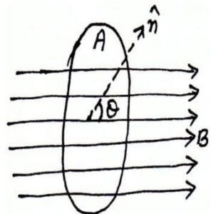
1 Magnetic Flux: It is defined as the total numbers of magnetic lines of forces passing perpendicular to a given surface. It is a scalar quantity and denoted by: –![]()
i.e. ![]()
or ![]()
![]() will be minimum if unit vector of surface is to applied magnetic field i.e. magnetic field is parallel to surface:-
will be minimum if unit vector of surface is to applied magnetic field i.e. magnetic field is parallel to surface:-
![]()
![]()
![]() will be maximum if area vector is parallel to applied magnetic field in this case
will be maximum if area vector is parallel to applied magnetic field in this case![]()
Dimensional Formula of Magnetic Flux:
as ![]()
or ![]()
![]()
or ![]()
SI unit of Magnetic Flux:
The S.I unit of magnetic flux is Weber. One Weber is the amount of magnetic flux produced when one Tesla magnetic field act on body normally over an area of![]() .
.
![]()
CGS unit of Magnetic Flux:
The ![]() unit of magnetic flux is Maxwell
unit of magnetic flux is Maxwell![]() . One Maxwell is the amount of magnetic flux produced when a uniform magnetic field of one gauss acts on a body normally on an area
. One Maxwell is the amount of magnetic flux produced when a uniform magnetic field of one gauss acts on a body normally on an area![]() .
.
![]() .
.
Relation between Weber and Maxwell
![]()
or ![]()
2. Electromagnetic Inductions:
The phenomenon of production of ![]() due to a change magnetic flux linked with a circuit is called electromagnetic induction. The generators and transformers are based on the principle of electromagnetic induction.
due to a change magnetic flux linked with a circuit is called electromagnetic induction. The generators and transformers are based on the principle of electromagnetic induction.
FARADAYSEXPERIMENTS:
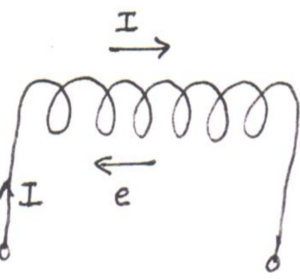
Exp.-1: Induced ![]() with a stationary coil and moving magnet:
with a stationary coil and moving magnet:
As shown in fig. take a coil connected to a sensitive galvanometer:-
Experiment:
- When the north pole of bar magnet is moved toward coil, the galvanometer shows a deflection, say to the right of the mark.
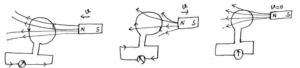
- When the north pole of the bar magnet is moved away from the coil, the galvanometer shows a deflection in opposite direction.
- When the magnet is held stationary, the galvanometer shows no deflection.
- If the South Pole is bringing toward coil the direction of current in coil becomes opposite.
Explanation or Conclusion:
When a bar magnet is moved toward or away from the coil, then the magnetic flux linked with the coil changes, as a result of which as current induces in the coil, which produce deflection in the galvanometer, but when there is no relative motion between coil and the magnet then there is no flux in coil, hence no current induces due to which galvanometer shows zero deflection.
Exp.-2:Induced ![]() with a stationary magnet and moving coil:
with a stationary magnet and moving coil:
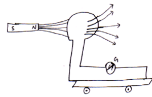
Similar results are obtained as from exp-1 when the magnet is held stationary and the coil is moved. When the relative motion between the coil and the magnet is fast, the deflection in the galvanometer is larger and when the relative motion between coil and magnet are slow, the deflection in galvanometer is small. Hence greater is the rate of change of magnetic flux linked with the coil greater is the induced current set up in the coil.
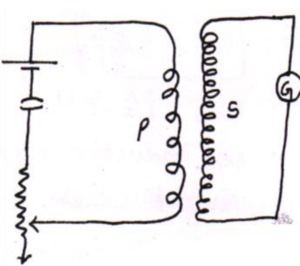
Exp.-3: Induced ![]() by verifying current in the neighboring coil:
by verifying current in the neighboring coil:
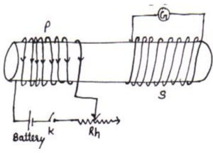
In Faradays third experiment there are two coil used. The first is called Primary coil connected to a battery through a key and Rheostat and the second coil are fixed near it called secondary coil connected to a galvanometer G. When constant current is flowed through the primary coil, then there is no any deflection in secondary coil but when current is increased or decreased in P coil then there is deflection in S coil.
As a current carrying coil behave as a magnet. Hence again this experiment is also conclude that a varying magnetic field produces current in the second coil.
From these experiments, we can conclude that:
- Whenever the amount of magnetic field linked with a coil changes then any induces in the coil hence current induces.
- The higher the rate of change of magnetic flux linked with the coil, greater is the induced

3. Law of Electromagnetic Induction: M.Imp.
There are two types of laws which govern the phenomenon of electromagnetic induction:
- Faradays law which gives us the magnitude of induced

- Lenz’s law which gives us the direction of induced
- Faradays laws of electromagnetic induction:
First Law:-
When the magnetic flux linked with the current changes, an ![]() is induces which remains till there is change in magnetic flux in circuit. This phenomenon is also called electromagnetic induction.
is induces which remains till there is change in magnetic flux in circuit. This phenomenon is also called electromagnetic induction.
Second Law:-
According to Faradays second law, the magnetic of induced ![]() is equal to rate of change of magnetic flux linked with the circuit.
is equal to rate of change of magnetic flux linked with the circuit. ![]()
According to this law, the ![]() induced in a circuit is directly proportional to rate of change of magnetic flux linked with the circuit.
induced in a circuit is directly proportional to rate of change of magnetic flux linked with the circuit.
I.e. suppose ![]() is the amount of magnetic flux at any time and
is the amount of magnetic flux at any time and ![]() is flux after
is flux after ![]() time then
time then
![]()
![]()
![]()
Or ![]()
Here ![]()
![]()
Or ![]()
Here ![]() sign indicate that the
sign indicate that the ![]() induced in the coil will oppose the applied magnetic field or magnetic flux as according to Lenz law. Which is explained below?
induced in the coil will oppose the applied magnetic field or magnetic flux as according to Lenz law. Which is explained below?
Example1: Flux associated with coil of resistance 10 Ω and number of turns 1000 is 5.5 × 10⁻⁴. If the flux reduces
to 5.5 × 10⁻⁵ wb in 0.1 s. The electromotive force and the current induced in the coil will be respectively.
Sol: The induced e.m.f. in coil is ![]() Where N is the number of turns in the coil.
Where N is the number of turns in the coil.
As Initial magnetic flux ![]()
Final magnetic flux ![]()
∴ Change in flux![]()
Time interval for this change![]()
∴ Induced emf in the coil![]()
Resistance of the coil, R=10 Ω.
Hence induced current in the coil is ![]()
Example 2. A square loop of side 10 cm and resistance 0.5 Ω is placed vertically in the east-west plane. A uniform magnetic field of 0.10 T is set up across the plane in the north-east direction. The magnetic field is decreased to zero in 0.70 s at a steady rate. Determine the magnitudes of induced emf and current during this time-interval.
Solution the angle θ made by the area vector of the coil with the magnetic field is 45°,
The initial magnetic flux is
![]()
Final flux, ![]()
The change in flux is brought about in 0.70 s. the magnitude of the induced emf is given by
![]()
And the magnitude of the current is
![]()
![]()
Example 3. A circular coil of radius 10 cm, 500 turns and resistance 2 Ω is placed with its plane perpendicular to the horizontal component of the earth’s magnetic field. It is rotated about its vertical diameter through 180° in 0.25 s. Estimate the magnitudes of the emf and current induced in the coil. Horizontal component of the earth’s magnetic field at the place is 3.0 × 10⁻⁵T.
Solution Initial flux through the coil,
![]()
Final flux after the rotation,
![]()
Therefore, estimated value of the induced emf is,
![]()
Current induced in the coil
![]()
Example4: at certain location in the northern hemisphere, the earth’s magnetic field has a magnitude of 42µT and points downward at ![]() to vertical. The flux through a horizontal surface of area 2.5
to vertical. The flux through a horizontal surface of area 2.5![]() will be (
will be (![]() )
)
Sol: The magnetic flux through any surface is![]()
Using the formula of flux φ= BA cosθ
We get the flux through the area as ![]()
= ![]()
- Lenz Law:
According to Lenz law, the ![]() induced in a coil due to change in magnetic flux will oppose the change flux which is cause of its production.
induced in a coil due to change in magnetic flux will oppose the change flux which is cause of its production.
Experimental Verification of Lenz Law:
The experimental set up used to verify Lenz law, is as shown in fig. firstly when we connect the terminal 1 & 2 then current flow in anticlockwise direction in the coil so that upper face of the coil behave as north pole and the deflection in galvanometer is toward right (says).
 Now connect the terminal second and third. And bring North Pole toward the coil, and then we see that again the deflection in galvanometer is toward right. This shows that upper face of coil is North Pole. Again when South Pole is brought toward coil then deflection is toward left means upper face is south. Hence in each case the induced current always opposes the change in magnetic flux which produces it. This verifies the Lenz law.
Show that Lenz laws obey law of conservation of Energy:
When a magnet is moved toward a coil then current induces in the coil here mechanical energy of motion of magnet is converted into electric energy and when motion is stopped then electric energy also becomes zero. Hence Lenz laws obey conservation of energy.
4. Fleming’s Right hand rule: M.Imp.
 This rule is used to find out the direction of induced current of a conductor moving in magnetic field. According to this rule, if we stretch, first finger, central finger and thumb in mutually
 ![]() direction such that 1st finger is in direction of
direction such that 1st finger is in direction of ![]() and thumb in direction of motion of conductor then central finger will give the direction of induced current.
and thumb in direction of motion of conductor then central finger will give the direction of induced current.
QUESTION5.Difference between Fleming left hand and right hand rule?
If a current carrying conductor is placed in magnetic field and we have to calculate direction of force than Fleming left hand rule is applied.
And if current induces in a conductor when placed in magnetic field, than the direction of induced force is calculated by Fleming right hand rule.
5. Various Methods of Producing Induced![]() :Imp
:Imp
There are three methods by which we can induce ![]() as
as ![]()
- By changing magnetic field B.
- By changing area A.
- By changing angle
 between magnetic field and normal to the surface.
As discussed below:
- By changing
 :
:
As we have seen in faradays experiments that when we change magnetic field by moving magnet toward or away from a coil then. ![]() Induces in the coil. Larger is change in B more is
Induces in the coil. Larger is change in B more is ![]() induced.
induced.
2. By changing A:
Consider a conductor CD of length ![]() moving with a velocity
moving with a velocity ![]() on a
on a ![]() shaped conducting rail situated in a magnetic field
shaped conducting rail situated in a magnetic field![]() . As conductor CD slides the area of the circuit changes. Then flux
. As conductor CD slides the area of the circuit changes. Then flux
![]()
![]()
Or ![]()
Or ![]()
Hence by changing area flux can be produced i.e. ![]() can be induced. This induced
can be induced. This induced ![]() is called motional
is called motional ![]()
- Induced
 by changing relative orientation of coil and magnetic field. By changing angle between B and area of the coil, flux can be changed due to which induces into coil.
Example 6:The magnetic flux () in a closed circuit of resistance 20 varies with time (t) according to the equation = 7 t2 – 4t where is in weber and t is in seconds. The magnitude of the induced current at t =0.25 s is
Solution: = 7t2 4t
![]() Induced emf: |e| =
Induced emf: |e| = ![]() = 14t 4
= 14t 4
![]() Induced current :i=
Induced current :i=![]() =
= ![]() =
= ![]() (at t = 0.25 s)= 2.5 10–2 A
(at t = 0.25 s)= 2.5 10–2 A
6. Energy Consideration in Motional ![]() :
:
As we know ![]() induced in a conductor moving
induced in a conductor moving ![]() to magnetic field is
to magnetic field is
![]()
Or ![]()
Also the force experienced by conductor in magnetic field is ![]()
Or ![]()
So power ![]()
Now conductor is pushed mechanically in the magnetic field, then mechanical energy per second is
![]()
Comparing eq. (i) and (ii) we can see that mechanical energy is concerted into electrical energy and then thermal energy.
Example 7:A train is moving from south to north with a velocity of 90 km/h.
The vertical component of earth’s magnetic induction is 0.4 × 10⁻⁴ Wb/m2. If the distance between the two rails is 1 m, what is the induced e.m.f. in its axle?
(a) 1 mV (b) 0.1 mV (c) 10 mV (d) 100 mV
Solution: Induced emf = Blv
= 0.4 10–4 1 ![]() = 10–3 V = 1 mV
= 10–3 V = 1 mV
Example8. A wheel with 10 metallic spokes each 0.5 m long is rotated with a speed of 120 rev/minin a plane normal to the horizontal component of earth’s magnetic field ![]() at a place. If
at a place. If ![]() = 0.4 G at the place, what is the induced emf between the axle and the rim of the wheel? Note that 1 G = 10–4 T.
= 0.4 G at the place, what is the induced emf between the axle and the rim of the wheel? Note that 1 G = 10–4 T.
Solution Induced
![]()
The number of spokes is immaterial because the emf across the spokes is in parallel.
Note that we have used
![]()
this gives ![]()
7. Eddy Currents: or Foucault current:- M.Imp
The current induced in the bulk piece of the conductors when the amount of magnetic flux linked with the conductor changes is called eddy current. This current is like eddy (whirlpool) in water also called Foucault current.
i.e. ![]()
or ![]()
![]()
The direction of eddy current may be given by Lenz law.
Applications of eddy current:
- Electromagnetic damping:
In case of dead beat galvanometer, eddy current is used to overcome damping of coil provide a value of current without delay.
- Induction Furnace:
Eddy current is used to provide a higher temperature in furnaces to make alloys of metals. A high frequency A.C. current is passed through a coil surrounding the metals. The large eddy current induces metals due to which they melt.
- Magnetic Breaks:
In electric trains, strong electromagnets are situated in the train, just above the rail. When electromagnets are turned on, flux changes due to which eddy current are produced which opposes the motion of the trains.
- Electric Power Meter:
In electric power meter there is a rotating shiny metallic disc. This disc rotates due to eddy current produced by magnetic field due to A.C.
- Induction Motor:
In Induction Motor a rotating magnetic field produces strong eddy current in a rotor which starts rotating in direction of the rotating magnetic field.
- Eddy current also used in speedometers of automobiles and energy meter, in deep heat treatment of the human body.
Undesirable/harmful effects produced by eddy current:
- It opposes the relative motion of bodies.
- Due to this there is lose of energy in from of heat.
- The excess heat produced in appliance may break their insulation and hence reduces their life.
Methods to Minimize eddy current:
To minimize eddy current, the metallic core should be taken in form of thin sheets in transformer, choke coil, motor etc. also each sheet should be insulated from each other and placed parallel to direction of magnetic field. By this we can reduce eddy current to a great extent.
8. Self induction: M.Imp
It is the property of a coil by virtue of which it oppose the any change in the strength of current flowing through it by inducing an ![]() in itself.
in itself.
Suppose at any instant of time, the magnetic flux linked with the coil is proportional to the amount of current ![]() flowing through it.
flowing through it.
i.e. ![]()
Or ![]()
Where constant of proportionality ![]() is called coefficient of self induction
is called coefficient of self induction
If ![]()
Hence coefficient of self induction is equal to the amount of magnetic flux linked with the coil when unit current flows through the coil.
Also ![]()
Or ![]()
If ![]()
Hence coefficient of self induction may also be defined as the amount of ![]() induced in the coil when rate of changes of current through the coil is unity.
induced in the coil when rate of changes of current through the coil is unity.
The unit of L is Henry
As ![]()
So ![]()
Hence one Henry is the amount of self induction when one ampere current flowing per second through a coil produces ![]()
Dimensions of self induction:
![]()
![]()
Example9: An average emf. of 0.20V appears in a coil when the current in it is changed from 5.0 an in one direction to 5.0 A in the opposite direction in 0.20 s. Find the self-inductance of the coil.
Sol: Using the formula ![]() we can find inductance of coil.
we can find inductance of coil.
- The average change in current w.r.t. time t,
-

- (ii) Using formula

9. Self induction of a long solenoid:
As we know field a long solenoid having ![]() turns is
turns is ![]()
Now magnetic flux through each turn of solenoid
![]()
Now total magnetic flux through ![]() turns
turns
![]()
But ![]()
![]()
![]()
![]()
![]()
For a medium ![]()
![]()
![]()
10. Mutual Induction: M.Imp
The phenomenon of production of induced ![]() in one coil due to change in amount of current is neighboring coil is called mutual induction.
in one coil due to change in amount of current is neighboring coil is called mutual induction.
Coefficient of Mutual induction:
At any instant of time the flux produced in the secondary coil is directly proportional to the amount of current passing through the primary coil.
i.e. ![]()
or ![]()
Where ![]() is a constant of proportionality called coefficient of mutual induction:
is a constant of proportionality called coefficient of mutual induction:
If ![]()
Hence coefficient of mutual induction may be defined as the amount of magnetic flux induced in the secondary coil when one ampere or unit current flow through the primary coil.
Also ![]()
If ![]() then
then ![]()
Hence coefficient of mutual induction may also be defined as the amount of ![]() induced in the secondary coil when rate of change of current in primary coil is unity.
induced in the secondary coil when rate of change of current in primary coil is unity.
The S.I. unit of mutual induction is Henry
As ![]()
One Henry is the amount of mutual induction when ![]() induces in the secondary coil by passing one ampere current per second through the primary coil.
induces in the secondary coil by passing one ampere current per second through the primary coil.
The coefficient of mutual induction depends upon shape, size, material, number of turn in the coil. Also on distance between the coils and their orientation
11. Mutual Induction of Two Long Co-axial Solenoid:
Suppose two long co-axial solenoids each of length ![]() again suppose
again suppose ![]() are the number of turns per unit length and
are the number of turns per unit length and ![]() are the radius of solenoids.
are the radius of solenoids.
If ![]() is the amount of current flowing in
is the amount of current flowing in ![]() then
then
![]()
 Here
Here ![]() is mutual induction of 1 due to
is mutual induction of 1 due to ![]()
Also magnetic field in ![]() due to
due to ![]() is
is
![]()
So flux through
![]()
![]()
or ![]()
Comparing eq. (i) and (ii)
![]()

![]()
![]()
Similarly we can show that
![]()
So ![]()
![]() or
or ![]()
or ![]()
This is the required expression for coefficient of mutual induction of two long co-axial solenoids.
12 Grouping of Coils:
Coils in Series:-
 Suppose two coils of coefficient of induction
 ![]() are connected in series. Suppose I is the amount of current flowing per second in coils then total
are connected in series. Suppose I is the amount of current flowing per second in coils then total ![]() of coils is
of coils is
![]()
Or ![]()
Or ![]()
Coils in Parallel:-
 Suppose two coils
 ![]() are connected in parallel and
are connected in parallel and ![]() is the amount of
is the amount of ![]() in each will by the flowing of current
in each will by the flowing of current ![]() through the coils. Then total current through the coils is I
through the coils. Then total current through the coils is I![]()
Differentiating both sides we get
![]()
Or ![]()
![]()
![]()
Hence grouping of coils is same to as that of grouping of the resistances.
SOME IMPORTANT MCQ
Q.1 Magnetic flux through a surface is independent of
(a) Area of surface (b) Strength of magnetic field
(c) Shape of surface (d) angle b/w area vector of surface and magnetic field
Q.2 c.g.s. unit of magnetic flux is
(a) Weber (b) Tesla (c) Maxwell (d) volt-sec
Q.3 One Weber is equal to
(a) ![]() (b)
(b) ![]() (c)
(c) ![]() (d)
(d) ![]()
Q.4 which of the following is not equal to Weber
(a) joule/ampere (b) ![]() (c) joule-sec/coulomb (d) volt/sec
(c) joule-sec/coulomb (d) volt/sec
Q.5 The cause of induced emf is
- magnetic flux (b) magnetic field (c) area (d) change in magnetic flux
Q.6 The magnetic flux linked with the coil is related to number of turn N of the coil as
(a)![]() (b)
(b)![]() (c)
(c)![]() (d)
(d)![]()
Q.7 With increase in number of turn of coil induced emf in the coil
(a) Increase (b) decrease (c) remain same (d) none of these
Q.8 Polarity of induced emf is given by
(a) Faraday’s law (b) Ampere’s law (c) Lenz’s law (d) Biot’ savrat’s law
Q.9 A coil is in the magnetic field then emf can be induced by
(a) By Changing magnitude of B (b) By changing area A of coil
(c) By changing orientation of coil w.r.t to B (d) all of above
Q.10 Lenz’s law is a consequence of the law of conservation of
(a) Charge (b) mass (c) energy (d) momentum
Q.11 The laws of E.M.I. have been used in the construction of a
(a) Galvanometer (b) voltmeter (c) electric motor (d) generator
Q.12 Direction of current induced in a conductor moving in a magnetic field is given by
(a) Fleming’s left hand rule (b) Fleming’s right hand rule (c) Ampere rule (d) Right hand thumb rule
Q.13 Which one is not an application of eddy current
(a) Magnetic brakes (b) speedometer (c) induction furnace (d) transformer
Q.14 The self-inductance of a coil is a measure of
(a) Electrical inertia (b) electrical friction (c) induced emf (d) induced current
Q.15 out of following, choose the correct relation
(a) 1 Henry=1volt/1ampere (b) 1 Henry=1ampere/1volt
(c) 1 Henry =1volt/1ampere/sec (d) 1 Henry =1volt/1ampere-sec
Q.16 The self inductance associated with a coil is independent of
(a) Time (b) induced voltage (c) current (d) resistance of a coil
Q.17 When rate of change of current through the coil is unity, the induced emf is equal to
(a) Number of turns in the coil (b) coefficient of self inductance
(c) Total flux linked with coil (d) none of above
Q.18 Coefficient of self inductance of coil depends on
(a) Number of turns (c) area of cross section
(c) nature of material on which coil is wounded (d) all of above
1