Unit-6 Optics
Chapter 9 Ray Optics and Optical Instruments
1 Optics:
It is that branch of physics which deals with the study of light and phenomenon due to light such as reflection, refraction, diffraction, interference; desperation, polarization and scattering etc. on the basis of nature of light i.e. ray nature and wave nature. Optics may be divided in to two parts:
1. Ray Optics
2. Wave Optics
Reflection, refraction, dispersion of light can be explained using ray optics.
Polarization, interference, Diffraction, etc can be explained using wave optics.
Light:
A form of energy which travel in form of radiations with or without medium and due to which vision process is possible is called light.
Form of Light:
Ray:
The path along which light travel from source to receiver called ray
Pencil of Ray:
A group of rays starting from a point called pencil of ray.
Beam of Ray:
A collection of ray with well defined boundary called beam.
2. Reflection of Light:
The phenomenon of bending or re-bouncing back of light in the same medium after striking a reflecting surface (mirror) is called reflection of light.
The vision process is possible only due to reflection of light.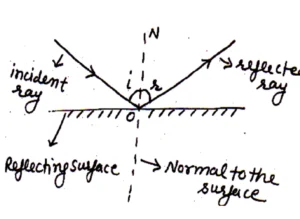
Laws of Reflection:-imp
1st Law:
The incident ray, reflected ray and normal to the surface lie in the same plane.
2nd Law:
The angle of incidence is equal to the angle of reflection.
i.e
Q. A ray of light incident at an angle 60o .Than what is the angle of reflection
Ans 60o
real and virtual images:-
Images can be real or virtual. If the reflected or refracted rays actually meet at the point I, then I is said to be a real image of the object O. But if the reflected or a refracted ray do not actually meet but only appear to diverge from the point I, then I is said to be the virtual image of the object O.
3. Types of Reflection of light:
Specular or Regular Reflection:
When the reflection surface is smooth and flat then the incident rays and reflected rays are parallels separately means all incident rays are parallel and all reflected rays are parallel, this types of reflection is called Specular reflection.
Diffused or Irregular Reflection:
If the reflecting surface is rough, then reflected rays are irregular i.e. not parallel to each other, such a reflection is called diffused reflection.
4. Reflecting Surface or Mirror:
Mirror is a device which reflects light which are falling on it.
It may be two types:
1. Plane Mirror
2. Spherical Mirror.
(A) Plane Mirror:
A mirror whose reflecting part is plane called plane mirror.
Characteristic of Image Formed by Plane Mirror:
The image formed by plane mirror is of same size to that of object.
The image formed by a plane mirror is at same distance behind the mirror as the object is in front of it.
Image formed by plane mirror is virtual and erect.
The image formed by plane mirror is latterly inverted. i.e
Some important facts about the plane mirror.
If the mirror is rotated at an angle θ then image rotates at angle 2 θ.
The minimum length of a plane mirror should be equal to half of the height of an object to see full size.
If a object moves toward plane mirror with a speed then image will move toward or away from mirror with

speed.
The linear magnification of a plane mirror is 1 and focal length=∞ and power of plane mirror is O.
The number of image formed between two planes inclined at an angle Q will be equal to
If is even then image formed will be
e.g: if Q=60
then image.
(ii) If is odd, then number of image formed will be
e.g: if Q=40
⟹ image.
i.e always odd number of images are formed between two inclined mirrors.
B. Spherical Mirrors:
A part of spherical reflecting surface is called spherical mirror. These are of two types:
(i) Convex Mirror:
A spherical mirror whose inner part is polished and outer part is reflecting called convex mirror called convex mirror.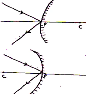
(ii) Concave Mirror:
A spherical mirror whose inner part is reflecting and outer part is polished called concave mirror or a mirror whose reflecting part is toward centre called concave mirror.
5. Some Important Terms Related to Spherical Mirrors:
Centre of Curvature (C):
The centre of sphere of which the spherical mirror is a part called centre of curvature.
Radius of Curvature (R):
The radius of sphere of which the spherical mirror is a part called radius of curvature.
Pole (Vertex):
The midpoint of the spherical mirror is called pole (P).
Principle Axis:
The line joining the C and P called principle axis.
Aperture:
The effective diameter of the mirror is called aperture.
Focus:
The point on the principle axis at which light after reflection from mirror meets or appears to meat called focus (F).
Focal Length:
The distance between pole and focus of a mirror is called focal length (f).
6. New Cartesian Sign Convention for Spherical Mirrors:-imp
All the distances should be measured from the pole of mirror.
The distances measured in direction of light are taken.
The distance measured in oppose to direction of light are taken.
The distance measured above the principle axis should be taken.
The distance below the principle axis should be taken.
7. Relation between Focal Length and Radius of Curvature of a Spherical Mirror:
For Concave Mirror:imp
Suppose a concave mirror of focal length f and radius of curvature R. Again suppose that a ray of light parallel to principle axis after reflection passes from the focus. As shown in fig.
Now from
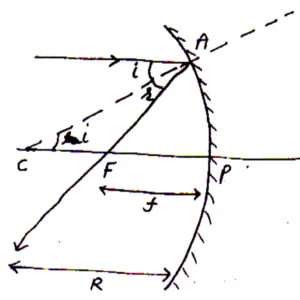
So
Also if aperture of the mirror is small then
From (i) and (ii)
Or we can say that F is midpoint of PC.
i.e.
Applying sign convention
Or
Or
For Convex Mirror: imp
Suppose a convex mirror of focus and radius of curvature R. again suppose that a rays of light coming from
, after reflection seems to be pass from the focus. As shown in fig.
Now In
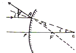
So
Also if aperture of mirror is small
Then
Comparing eq. (i) and (ii) we get
i.e is midpoint of
and
so
Applying new Cartesian sign convention,
or
8.Mirror Formula or Mirror Equation: imp
A relation between of a mirror is called mirror formula.
Mirror Formula for Concave Mirror when Real Image is Formed:
Suppose a concave mirror of centre C, focus F and pole P. Again suppose that the rays coming from an object AB placed beyond centre. After reflection form real and inverted images I.
Now from diagram, and
are similar so
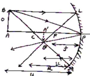
Again and
are similar
so
Comparing eq. (i) and (ii) we get
Now applying bew cartesian sign convenstion we get
Using in eq. (iii) we get
⟹
Or
Or
Deviding both sides by we get
But
⟹
Which is the required expression for mirror formula for concave mirror when real image is formed.
Mirror Formula for Concave Mirror when Virtual Image is formed:
Suppose a object AB is placed between pole and focus of a concave mirror and is its virtual image formed behind the mirror.
Now from diagram and
are similar So
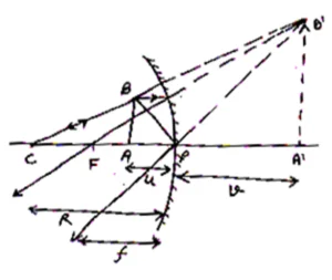
Again and
are similar so
from (i)and (ii)
Applying new cartesian sign convension, we get
,
Using in eq. (iii) we get
Or
Or
Dividing both sides by we get
But
so
Which is the required expression for mirror formula for concave mirror when image is formed is virtual.
Question1: An object is placed in front of a concave mirror at a distance of 7.5 cm from it. If the real image is formed at a distance of 30 cm from the mirror, find the focal length of the mirror. What would be the focal? Length if the image is virtual?
Solution: Case I: When the image is real.
We have u = – 7.5 cm; v = – 30 cm; f =?
We know
Or, f =
=
= – 6 cm
Case II: When the image is virtual: In this case,
u = – 7.5 cm v = + 30 cm
We know
or, f =
= – 10 cm
Mirror Formula for Convex Mirror:
Suppose a object AB is placed near a convex mirror and is its virtual and diminished image fromed, as shown in fig.
So
Also and
are similar
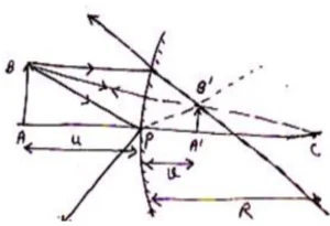
Comparing eq. (i)and (ii)
Applying new cartesian sign convension
Using in eq. (iii) we get
Or
Or
Deviding both sides by we get
Or
9. Linear Magnification of Mirror (): imp
It is defiened as the ratio of height of the image to the height of the object
i.e
(i).Magnification of concave Mirror when real image is formed.
For concave mirror, we know that 
Applying sign conventions
So
Or
(ii).Magnification of Concave mirror when virtual is formed for virtual image
As
Applying sign convension we get 
So
i.e
(iii).Magnification produced by convex mirror for convex mirror
Now applying new cartesian sign convention
⟹
i.e
If then image will be larger then object.
If then image will be smaller then object
If then size of image will be equal to size of object (plane mirror)
If image will be real and if
image will be virtual.
10. Magnification in term of :
As
multiplying both side by u we get
⟹
or
As
or
As
multiplying both sides by v, we get
⟹
⟹
Or
Question2: An object 5 mm high is placed 30 cm from a convex mirror whose focal length is
20 cm. Find the position (in cm), size (in mm) and nature of the image.
Solution: We have, u = – 30 cm; v =? f = + 20 cm
We know
Or, v =
= = + 12 cm
The image is formed 12 cm behind the mirror, it is virtual.
Now, m =
Or, I =
= + 2 mm
Hence the height of the image = 2mm the positive sign indicates that the image is erect.
Question3: An object 2 mm high is placed 150 mm from a concave mirror of focal length 5 cm. Find the position (in mm) and size (in mm) of the image.
Solution: We have u = –15 cm; v =? f = – 5 cm
We know that
Or, v =
= – 7.5 cm
= –75 mm
The image is formed at a distance of 75 mm in front of mirror.
Now, m =
or,
Or, I = –1 mm
The negative sign indicates that image is inverted.
Q 4. A small candle, 2.5 cm in size is placed at 27 cm in front of a concave mirror of radius of curvature 36 cm. At what distance from the mirror should a screen be placed in order to obtain a sharp image? Describe the nature and size of the image. If the candle is moved closer to the mirror, how would the screen have to be moved?
Solution: The object is kept between ƒ and C. So the image should be real, inverted and beyond C.
To locate the sharp image, screen should be placed at the position of image.
The focal length
Using the formula
Size of the image can be calculated by
So, the image is inverted and magnified. Thus in order to locate the sharp image, the screen should be kept 54 cm in front of concave mirror and image on the screen will be observed real, inverted and magnified.
If the candle is moved closer to the mirror, the real image will move away from the mirror, hence screen has to be shifted away from the mirror to locate the sharp image.
Question 5: A 4.5 cm needle is placed 12 cm away from a convex mirror of focal length 15 cm. Give the location of the image and the magnification.
Describe what happens as the needle is moved farther from the mirror.
Solution: A convex mirror always form virtual image, which is erect and small in size of an object kept in front of it.
Focal length of convex mirror ƒ = + 15 cm
Object distance u = – 12 cm.
Using mirror formula
Therefore, image is virtual, formed at 6.67 cm at the back of the mirror.
Magnification
It shows the image is erect, small in size and virtual. When the needle is moved farther from mirror the image also move towards focus and decreasing in size.
As u approaches v approaches focus but never beyond ƒ.
11. Application or Uses of Spherical Mirror: imp
Concave Mirror:
Dentist, ENT specialist, for saving and make up, in cinema projector, in reflecting type telescope, in solar cooker, in search light, motor head light, in torch, in dish antenna.
Convex Mirror:
As rear view mirror, in reflector for street lighting, in big shops to monitor the activities of customers
Unit: 6 (b) Refraction of Light
12. Refraction of Light:
The phenomenon of deviation or bending of light rays from their original path while passing from one medium to another is called refraction.
Refraction of light occurs because light changes its velocity when it moves from one medium to another medium.
On refraction both velocity and wavelength of light changes but frequency remains unchanged.
13. Laws of Refraction of Light: imp
The incident ray, refracted ray and normal to the surface meet at a point. 
Snell’s Law: The ratio of sine of angle of incidence to the sine of angle of refraction is constant for a pair of media.
i.e
Here is called refractive index of second media w.r.t first medium.
14. Refractive Index: or Absolute Refraction Index: imp
The ratio of velocity of light in vacuum to the velocity of light in a medium is called absolute refractive index or simply refractive index
i.e where
Absolute refractive index may not be less than one because.
Relative Refraction Index:
Suppose there are two medium of refractive index and
then
called relative refractive of two w.r.t one.
Or
Or
Clearly smaller, the refractive index of a medium larger the velocity of light in that medium.
Refractive indexes are a scalar quantity and have no units.
A medium having higher refraction index called optical denser medium and a medium having lower refraction index called rare medium.
Note: Optical density is differ then mass density i.e for example, the mass density of turpentine is less then water but it is more optical denser then water.
Question6: If wavelength of light in glass is 7200 Å, then find the wavelength of same light (in Å) in water.
(w = 4/3, g = 3/2)
Solution:
so Å
= 8100 Å
Question: 7 The refractive index of glass is 1.5. What is the speed of light in glass?
Answer: Given, Refractive index of the glass
Speed of light in vacuum
As we know, Refractive index of a medium
.
Where is the speed of light in that medium.
So from here,
Hence the speed of light in water is
15. Principle of Reversibility of Light (Refraction through a Glass Slab): imp
Suppose a ray of light PQ incident at Q point on a glass slab as shown in fig. Applying Snell’s Law at point Q we get 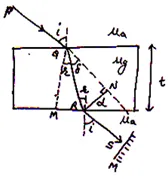
Now the ray of light again suffer refraction at point R so applying again Snell’s Law at R we get
Multiplying eq. (i) and (ii) we get
Or
Or
Here we can see that when a mirror is placed ⊥ to the path of light, then light regain its original path. This phenomenon is called principle of reversibility of light.
16 Lateral Shift: imp
The perpendicular distance between incident ray and emergent ray is called lateral shift. In above fig. d is the lateral shift.
Consider . In QRN
⟹
Again, consider
In QMR
⟹
Here t is the thickness of glass slab.
Using in eq. (i) we get
As
⟹
Or
Hence lateral shift increase with thickness of glass slab, increase in incidence angle and refractive index of glass slab
Question8: A ray of light is incident at an angle of 60° on one face of a rectangular glass slab of thickness mm and refractive index
. Calculate the lateral shift produced in mm.
Solution: Here i = 60°; = and t =
m
Now, =
or, sin r =
= r = 300
Now, lateral shift,
d =
= 2mm
17. Refraction through Multiple or Compound Refracting Media: imp
In fig. shows the refraction of light from air to water then to glass then glass to again air.
Now for the ray going air to water
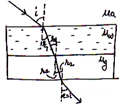
For the ray going from water to glass
Similarly for the ray going glass to air
Multiplying the above three equations,
we get
Or
Or
But
⟹
Or
Thus by knowing the refractive index of any two medium, we can calculate the refractive index of third medium connected with first two.
18. Practical Applications of Refraction:
Real and Apparent Depth imp
A coin lying at the bottom of a bucket full of water appears to be raised due to refraction of light. Explained as below.
Suppose a coin is placed at point O in a bracket, A ray of light coming normally will go along OA and when seen the coin from B it seems to be coming from. So here, OA is real depth and
is apparent depth. In fig. applying Snell’s law at B we get
In

And in
Using in eq. (i)
Or
If point B lies near to point A
then and
⟹
Or
Here it should be noted that so apparent depth is always smaller then real depth.
Normal Shift:
The height through which a object appear to be raised in denser medium called normal shift.
i.e.
⟹
Or
Normal shift will be large if thickness of water tank is large and small if refractive index is small.
Question 9 . A tank is filled with water to a height of 12.5 cm. The apparent depth of a needle lying at the bottom of the tank is measured by a microscope to be 9.4 cm.
What is the refractive index of water? If water is replaced by a liquid of refractive index 1.63 up to the same height, by what distance would the microscope have to be moved to focus on the needle again?
Solution: We know the relation
Now if the water is replaced by other liquid, the apparent depth will change and microscope will have to be further moved to focus the image.
So
Now the microscope will have to shift from its initial position to focus on the needle again which is at 7.67 cm depth.
Shift distance = 9.4 – 7.67 = 1.73 cm.
Apparent shift in the position of sun at sunrise and sunset:
Due to atmospheric refraction, the sun is visible before actual sunrise and after actual sunset.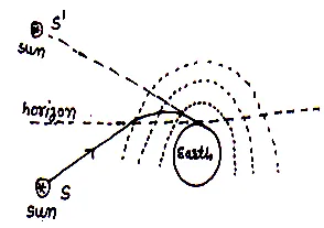
As we know near the surface of earth, the density of gasses is large so it behaves like denser medium. When a ray of light comes from sun below horizon toward earth, then light travel from rare to denser medium. Due to multiple refractions , the apparent sun seen above the horizon before two minute then its actual sunrise. Similarly at sun set it seen after its sunset. Therefore, we can say that our day becomes 4 minute bigger than actual.
There are some other phenomenon’s related to refraction of light given below:
Twinkling of Stars
Bending of an object placed in waters tank
Visibility of two objects immersed in water
Bigger size of sun at sunrise and at sun set
19.Total Internal Reflection (TIR):m. imp
The phenomenon in which a ray of light travelling at an angle of incidence greater then critical angle from denser to rare medium is totally reflected back into the denser medium is called TIR.
Necessary Conditions for Total Internal Reflection:
Light should travel from denser medium to rare medium.
The angle of incidence should be greater than critical angle.
Critical Angle:
The angle of incidence in the denser medium at which angle of refraction in the rare medium becomes 90° called critical angle.
Relation between Critical Angle and Refractive Index:
As from Snell’s Law 
Or
When then
⟹
Or
Hence, refractive index of a medium is reciprocal of sine of critical angle.
During TIR, the whole incidence light energy is reflected back in the denser medium.
Greater is the refractive index of denser medium, smaller will be its critical angle.
e.g: ⟹
⟹
20. Some Applications of Total Internal Reflection: imp
Sparkling or Brilliance of Diamond:
The Brilliance of diamonds is due to total internal reflection. As the refractive index of diamond is very large . So its critical angle is very small
. Thus when diamond is shaped in such a way that when light fall on its faces then the angle of incidence is always greater then critical angle. So light remains in diamond, due to which diamond spark
(ii) Mirage:
Mirage is an optical illusion of water observed generally in deserts when the inverted image of an object is observed along with the object itself in a hot day.  Because in hot day the gases near earth behave as rare medium and upper air behave as denser medium. The ray of light from tree reaches the surface of earth at an angle greater then critical angle here the incident light suffers total internal reflection. When the observer sees the object as well as image, he gets the impression of water pool near the object.
The mirage formed in hot region called inferior mirage and mirage formed in cold regions called superior mirage or looming.
(iii) Totally Reflecting Prism (Porro-Prism):
A right-angled isosceles prism called porro-prism can be used in binocular.  When a ray falls normally on any face of such a prism, it is incidence at an angle greater then critical angle of glass (about 42°). Hence the ray is always totally reflected.
(iv) Optical Fiber:
Optical fibers are used in the transmission of signal through a long distance. It consists of a fine glass coated by a thin layer of a material having refractive index less then glass strand. It consists of three main parts:
Core:
The central cylindrical core made of high quality glass plastic.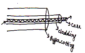
Cladding:
It is also made up by glass 1 fiber having refractive index lesser then core material.
Coating:
It is a plastic jacket used for safety and strength.
Propagation of Light in Optical Fiber:
When light is incidental at one end of optical fiber at an angle greater than critical angle then it get total internal reflection. Due to multiple total internal reflections a signal or light, moves from one end of fiber to another end without much lose of energy.
21. Spherical Reflecting Surfaces:
A refracting surface whose curved surface is a part of sphere called spherical surface. 
Concave Spherical Refracting Surface:
A spherical refracting surface, which is concave toward rare medium, is called concave spherical refracting surface.
(ii) Convex Spherical Refracting Surface:
A spherical refracting surface, which is convex toward rare medium, which is rare medium, is called convex toward refracting surface,
22. Term Related to Spherical Refracting Surface:
Pole:
A midpoint spherical refracting surface is called pole.
Centre of Curvature:
The centre of sphere, whose refracting surface is a part called centre of curvature (c).
Radius of Curvature:
It is the radius of sphere, whose refracting surface is a part denoted by R.
Principle Axis:
A line passing through pole and centre of refracting surface is called principle axis.
Aperture:
The effective diameter of refracting surface, which is exposed to the light, is called aperture (AB).
23. New Cartesian Sign Conventions: imp
All the distance should be measured from the pole of mirror.
The distance measured in direction of light are taken and in opposite to direction of light are taken
.
The distance above the principle axis should be taken and below the principle axis should be taken
.
Assumptions:
While studding refraction through refracting surfaces we assume that:
The aperture of refracting surface is small.
The object is a point object and lies on principle axis.
The incident ray, refracted ray and normal to the surface makes small angles with principle axis.
24. Refraction at a Spherical Surface:m.imp.
Refraction through Convex Surface when Object is in Rarer Medium and Image Formed is Real:
Suppose a convex refracting surface of centre C and pole P. again suppose that a object o is placed for away from pole of the mirror and I is image formed by the mirror, as shown in fig.
Step1: Determination of and
.

From
and from
⟹
If than from
And from
Similarly from
Using in eq. (i) and (ii) we get
And
Step 2: Applying Snell’s Law:
(∵i & r are small so
)
Or
Using eq. (iii) and (iv) we get
Or
Step 3: Now applying new Cartesian sign conventions:
As aperture of surface is small so
Using in eq. (v) we get
Or
This is the required expression for refraction through refracting surface.
(b) Refraction through Convex Refracting Surface When Object is Placed in Rare Medium and Image Formed is Virtual:
Suppose a convex refracting surface of pole P, centre C. Again, suppose that an object O is placed near to the pole of the mirror and I is virtual image formed behind the object. As shown in fig.
Step 1:Determination of and
:-

As from diagram
If are small then
Now from
And from
Step 2: Applying Snell’s Law:
From Snell’s law as angle and
are small so
⟹
Using eq. (i) and (ii) we get
Or
Step 3: Applying new Cartesian sign Conventions.
As aperture of the refracting surface is small so
Using in eq. (iii) we get
Or
Which is the required expression for refraction through convex refracting surface when object in rare medium and image formed is virtual.
(c) Refraction at Concave Spherical Surface when Object lies in Rare Medium:
Suppose a concave refracting surface of pole P, centre C, again suppose that a object is placed at a distance u from the pole and I is the virtual image formed. As shown in fig.
Step 1: Determination of and
.
As from diagram for small, we may write
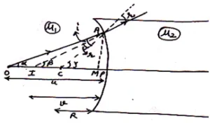
from
Again from
Step 2: Applying Snell’s Law:
As and
are small so from Snell’s law we may write
⟹
Using eq. (i) and (ii) we get
Or
Step 3: Applying new Cartesian sign Conventions.
If aperture of the surface is small than
Using in eq. (iii) we get
Or
(d) Refraction at Convex Spherical Surface when Object lies in denser medium image formed is real:
Suppose an object O is placed in denser medium of refractive index and the formation of image I of object is a shown in fig.
Step 1: Determination of and
.
As from diagram for small, we may write

And from
Again from
Step 2: Applying Snell’s Law:
As and
are small then Snell’s law we may written as
Or
Using eq. (i) and (ii) we get
Or
Step 3: Applying sign Conventions.
If aperture of the surface is small than
Using in eq. (iii) we get
Or
Or
This is the required expression for refraction through convex refracting surface.
(e) Refraction at Convex Surface When Object Lies in denser Medium and Image Formed is Virtual:
Suppose an object O is placed in denser medium of refractive index and the formation of image I is a shown in fig.
Step 1: Determination of and
.
As from diagram for small, we may write

Now from
Again from
Step 2: Applying Snell’s Law:
For small and
Snell’s law we may written as
⟹
⟹
Or
Step 3: Applying New Cartesian sign Conventions.
If aperture of the spherical refracting surface is small then
Using in eq. (iii) we get
Or
Which is the required expression for refraction through convex refracting surface, when object is placed in denser medium and image formed is virtual
(f) Refraction at Concave Spherical Surface when Object Lies in Denser Medium:
Suppose an object O is placed in denser medium of a concave refracting surface and I is its virtual image formed in the surface as shown in fig.
Step 1: Determination of and
.
As are small so we may write

Now from
And from
Step 2: Applying Snell’s Law:
For small and
Snell’s law we may written as
⟹
Using eq. (i) and (ii) we get
⟹
Or
Step 3: Applying New Cartesian sign Conventions.
If aperture of the spherical refracting surface is small then
Using in eq. (iii) we get
Or
Which is the required expression for refraction through concave refracting surface, when object is placed in denser medium.
25. Lens:
A lens is piece of transparent material bounded by two refracting surfaces out of which at least one is curved. Various types of lenses are as given below:
Uses:
Lenses are commonly used to correct vision deflects in human eyes. They are also used in microscopes, telescopes and cameras, cinemas, photography.
Terms Used in Lenses:
Optical Centre:
The point in the lens through which the light passes un-deviated
Principle Focus (F):
The point on the principle axis on which the rays parallel to principle axis after refraction meats or appear to meet.
Assumptions made to derive Lens maker’s Formula:
The lens is this and all the distances should be measured from optical centre of the lens.
The aperture of the lens is small.
The object is point object and lies on principle axis.
The angles made by incident and refracted ray are small.
New Cartesian Sign Convention:
All the distance should be measured from the centre of the lens.
The distance measured in direction of light are taken and in opposite to direction of light are taken
.
26. Lens Maker’s Formula: m.imp
A formula, which gives the relation between focal length radius of curvature (R) and refractive index (
) of the lens is called lens maker formula. It is used to make a lens so called lens maker’s formula.
Lens Maker’s Formula for Convex Lens:
Refraction at Surface:
Suppose an object O lies at principle axis of a lens, in rare medium. A ray of light incident at
surface of lens and if there is no any surface
then I, is the image of the object O.
Since object lies in rare medium, so we have 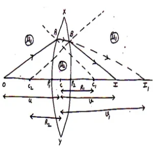
Now refraction at surface.
In reality the ray refracted by again refracted at B by the second surface
and finally form image at I. in this case I1 act as the virtual object placed in the denser medium. So we may write
Or
Adding eq. (i) and (ii) we get
Or
Or
If object lies at then image will form at focus i.e
if
⟹
Or
The above relation is called lens maker’s formula.
Question 10 .Double-convex lenses are to be manufactured from a glass of refractive index 1.55, with both faces of the same radius of curvature. What is the radius of curvature required if the focal length is to be 20 cm?
Solution: Both faces should be of same radius of curvature
So lens makers formula
⟹
Or
So, the radius of curvature should be 22 cm for each face of lens.
27 Derivation of Lens Maker’s Formula for Concave Lens:
The derivation is same to as that of convex lens.
Question11: Calculate the focal length of a biconvex lens in air if the radii of its surfaces are 60 cm and 15 cm. Refractive index of glass = 1.5
Solution: Consider a light ray going through the lens as shown.
It strikes the convex side of 60 cm radius and concave side of 15 cm radius while coming out
R1 = + 60 cm = – 15 cm
or,
=+ 24 cm
Question12: Calculate the focal length of a concave lens in water (w =
) if the surface have radii equal to 60 cm and
20 cm. g = 1.5
Solution: R1 = 20 cm; R2 = + 60 cm
We have
=
f = – 120 cm
28 Thin Lens Formula: imp
The relation between the distance of object, image and focal length
of a lens is called thin lens formula or lens formula.
(a)Lens Formula for Convex Lens when Image Formed is real:
Suppose a object AB is placed at the principle axis of a convex lens and is the real and inverted image of object AB, Now as from fig.
And
are similar so

Again and
are similar so
As
From eq. (i) and (ii)
As according to sign convention all the distances should be measured from the optical centre
so
Using in eq. (iii) we get
Or
Dividing both, sides by
we get
Or
Or
This is the lens formula.
(b)Lens Formula for Convex lens when virtual Image is formed:
Suppose an object AB is placed near to a convex lens of focal length and
is its virtual and enlarged image formed behind the object as shown in fig.
Now as from diagram
and
are similar so

Again and
are similar so
but
So
Comparing eq. (i) and (ii) we get
Applying new Cartesian sign convention we get
Using in eq. (iii) we get
⟹
Or
Multiplying both, sides by
we get
Or
This is the lens formula.
(c)Lens Formula for Concave Lens:
Suppose an object AB is placed at the principle axis of a concave lens and is its virtual and diminished image formed between focus F and centre C. as shown in fig.
and
are similar so

Again and
are similar so
But so
From eq. (i) and (ii)
Now applying new Cartesian sign convention we get.
Or
Using in eq. (iii) we get
⟹
Or
Dividing both, sides by
we get
Or
Or
This is the required expression for lens formula for concave lens.
29 Linear Magnification: m.imp
Linear magnification of a lens is defined as the ratio of size of image to the size of an object. It is denoted by m.
i.e
Linear magnification in term of and
:
Linear Magnification for Convex Lens when image Formed is real.
As linear magnification is 
As and
are similar
So
Applying sign convention, we get
⟹
Or is
for convex lens. Image will be real and inverted.
Linear Magnification for Convex lens when Image formed is virtual:
For virtual image
As and
are similar

So
Now applying new Cartesian sign convention, we get
So linear magnification
=
or image will be virtual and erect.
Linear Magnification for Concave Lens:
As and
are similar
So ,
by sign convention we get
Linear magnification
i.e image will be virtual and erect.
30 Linear Magnification in term of and
:
As we know for a lens
Multiplying both side by we get
Or
Linear magnification in term of v and f
As we know for a lens
Multiplying both side by we get
Or
or
Question 13. A beam of light converges at a point P. Now a lens is placed in the path of the convergent beam 12 cm from P. At what point does the beam converge if the lens is
(a) a convex lens of focal length 20 cm, and
(b) a concave lens of focal length 16 cm?
Solution:
(a) The convex lens is placed in the path of convergent beam. Using lens formula
The image 1 is formed by further converging beams at a distance of 7.5 cm from lens.
(b) A concave lens is placed in the path of convergent’ beam, the concave lens further diverge the light.
Using lens formula
.
The image I is formed by diverged rays at 48 cm away from concave lens.
Question 14. An object of size 3.0 cm is placed 14 cm in front of a concave lens of focal length 21 cm. Describe the image produced by the lens.
What happens if the object is moved further away from the lens?
Solution: Object of size 3 cm is placed 14 cm in front of concave lens.
Using lens formula
Formula for magnification
=
So, the image is virtual, erect, of the size 1.8 cm and is located 8.4 cm from the lens on the same side as object. As the object is moved away from the lens, the virtual image moves towards the focus of the lens but never beyond it.
The image also reduces in size as shift towards focus.
Question 15. The image of a small electric bulb fixed on the wall of a room is to be obtained on the opposite wall 3 m away by means of a large convex lens.
What is the maximum possible focal length of the lens required for the purpose?
Solution: Let the object be placed x m in front of lens the distance of image from the lens is (3 – x) m.
Using lens formula
so
Condition for image to be obtained on the screen,
i.e. real image 9 – 12ƒ > 0 or 9 > 12ƒ or f < 0.75 m. so, maximum focal length is 0.75 m.
31 Power of a Lens: imp
The ability of a lens to converse or diverse a beam of light falling on it is called power of lens. It is defined as the reciprocal of the focal length in meter
i.e
As we know focal length of a lens is
So
Si unit of power is (D)
i.e
Hence, the power of a lens is one whose focal length is one meter.
32 Thin Lenses in Contact: imp
Suppose two thin lenses of focal length are placed in contact with each other. Let a object O is on principle axis and
is its image if there is no second lens. So we may write

But there is second lens also, and we get final image I instead of . In this case
act as virtual object of I. so we may write
Adding eq. (i) and (ii) we get
Or
Or
Or
Where F is equivalent focal length of the combination of lenses.
For n lens we may write
Also, power
If one lens is convex and one is concave then focal length of combination becomes
And
Power of plane glass lens is zero.
Question 16 . What is the focal length of a convex lens of focal length 30 cm in contact with a concave lens of focal length 20 cm? Is the system a converging or a diverging lens? Ignore thickness of the lenses.
Solution: Equivalent focal length of the combination
Or
Hence, system will behave as a diverging lens of focal length 60 cm.
33. Spherical Aberration in Lenses:
It is the inability to focus all the rays of light to a single point by lens. It can be over combed by using narrow beam of light and by using cylindrical lens.
Chapter 6(c): Dispersion of Light
34 Prism:
A prism is a homogeneous transparent refracting medium bounded by at least two non-parallel plane surfaces inclined at an angle. As we have studded total internal reflection through a prism. Now in this chapter we will study two more phenomenon associated with prism.
Deviation (ii) Dispersion
Refraction Though a Prism:
Calculation of angle of Deviation of Prism: imp
Suppose a ray of light fall on a prism of angle of prism A and suffer refraction through prism, as shown in fig. If light suffer no refraction then it moves without any deviation.
Here the angle between incident ray and emergent ray is called angle of deviation ().

As from diagram, in
Now again from quadrilateral
Comparing eq. (i) and (ii) we get
And from
Or
If is the refraction index then from Snell’s Law
⟹
Similarly
Using in eq. (iv) we get
⟹
Or
If then
can be calculated using eq. (v) and for large
we use eq. (iv)
(b)Derivation of Prism Formula: imp
As we know
⟹
Or
Or
Now will be minimum if
⟹ =
Or
If from
So from eq.
we get
⟹
And from eq.
we get
⟹
Now from Snell’s law
We get
This expression is called prism formula.
Question17: A ray of light is incident on one face of a prism ( =) at an angle of 60°. The refracting angle of the prism is also 60°.
Find the angle of emergence and the angle of deviation.
|
Solution: Angle of incidence = i = 60° At point P, sin r1 = 300 |
|
Using r1 + r2 = A,
we get r2 = A – r1 = 60° – 30° = 300
At point Q, =
or sin e = e = 600
Question18: A ray of light makes an angle of 60° on one of the faces of a prism and suffers a total deviation of 30° on emergence from the other face. If the angle of the prism is 30°, show that the emergent ray is perpendicular to the other face.
Solution: The angle of deviation = (i1 + i2) – A
here, = 30°, i1 = 60°; A = 30°
Hence 30° = 60° + i2 – 30°
= 30° + i2
i2 = 0
The angle of emergence is zero. This means that the emergent ray is perpendicular to the second face.
Question19: The refracting angle of the prism is 60° and the refractive index of the material of the prism is. Calculate the angle of minimum deviation in degree.
Solution: Here, A = 60°; =
Now, =
or, =
Or, sin
= sin 30° =
or, =600
m = 600
36 Dispersion of Light through a Prism:
The phenomenon of splinting of white light into seven colors on passing through a prism is called dispersion of light.
The pattern of these seven colors is called spectrum of light and called VIBGYOR means violet, indigo, Blue, Green, Yellow, Orange and Red.
Cause of Dispersion:
According to Cauchy’s formula, the refractive index of a material depends upon the wavelength
of light.
As
Where A, B, C are constants, Also for prism having small refracting angle, the angle of deviation is
As different color have different-different wavelength so different refractive index, again due to different refractive index they deviate at different angles so dispersion of light occurs.
Now comparing and
for colors using eq. (i) and (ii) we observe that as
Because larger the wavelength, smaller are deviations.
37 Angular Dispersion: imp
It is defined as the difference in the angles of deviations between two extreme colors i.e violet and red color.
If
And
Then angular dispersion
But as we know
So for violet color
And for red color
So
Or
Hence, angular dispersion depends upon angle of prism and nature of material of the prism.
38 Dispersive Power: imp
It is defined as the ratio of angular dispersion to the mean deviation produced by a prism. It is represented by w.
The mean deviation of a prism is taken for yellow color as 
And as angular dispersion
So dispersive power becomes
Or
Or
39 Rainbow:
A rainbow is a spectrum of colors in from of circular arcs, which forms in sky due to total internal reflection, and dispersion of light by rain drops during or after the shower (rain).
The essential condition for observing rainbow is the head of person should be in opposite to sun.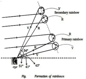
Rainbow have two parts:
Primary Rainbow:
The inner of the two bows is primary rainbow; it forms due to two refraction and one total internal reflection at an angle 42. In primary rainbow violet color is in low at 41
and red color on top at 43
. This rainbow is bright.
Secondary Rainbow:
The outer of the two bows is secondary rainbow, it is formed due to two refraction and two total internal refractions. Its lower color is red 51 and upper color is violet at 54
. The mean position of rainbow formation is 52.5
. it is less bright then primary rainbow.
40 Scattering of Light:
The process of radiating the light by the particles in all directions by absorbing light is called scattering of light. The atom or molecules which scatter the light is called scatter.
According to ray Leigh, the intensity of scattered light varies inversely to the forth power of wavelength.
i.e
Means for scattering of light the size of particle should be small and comparable of wavelength of light. If size of particle is large then scattering does not observed i.e all wavelengths emits equally.
41 Some Phenomenon Associated with Scattering of Light: imp
Blue Color of Sky:
When white light from sun entre into earth’s atmosphere then by small sized particle scattering occurs. As wavelength is violet color is small as compared to red color, so its scattering is more as compare to other colors, that’s why sky looks blue, as it is comparable to size of particles.
Reddish Color of Sun at Sun Rise and Sun Set:
At sunrise and sun set the sun is at large distance. So different colors having smaller wavelength, scatter in the atmosphere and red color suffer small scattering due to large wavelength. So reaches at over eyes. So sun looks reddish at sun rise and sun set.
While Color of the Clouds:
As clouds are very near to the earth and consist of large sized water molecules, dust etc. so scattering of all the colors is equals, these scattered color merge together and act as white color. So clouds appear white.
Danger Signals are Red:
As red color have large wavelength so small deviation or scattering and can be seem from a large distance so danger signals are formed red colored.
Chapter: 6(d) Optical Instruments
The device, which works on the principle of refraction, reflection or rectilinear propagation of light are called optical instruments. This instrument helps human eyes to see highly magnified images of tiny objects like microscopes and to see for off object by the helps of terrestrial or astronomical telescope.
42 The Human Eye (Natural Camera):
The main parts of human eye are:
Cornea:
The outermost transparent parts of eye, which allow light to fall on eye called cornea.
Iris and Pupil:
The iris is a colored ring, which has a circular hole in its centre, called pupil; the iris can control the amount of light by adjusting the size of pupil.
Lens:
It is a double convex lens behind the pupil and held by cilliary muscles its refractive index is about 1.43. it focus the image of an object on retina.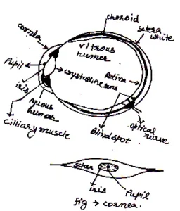
Retina:
It is a screen, which obtain the image of an object. It is consist of rods and cones, which sense light intensity and color respectively. They transmit electrical signals via optical nerve to the brain.
Aqueous and Vitreous Hummer:
These are the fluid, which protect eye and clean.
Working of Human Eye:
When we look at an object, light from the object enters the pupil of the eye and fall on the eye lens. The eye lens forms a real and inverted image on the retina of the eye. The retina of the eye contains special cells in the shape of cones and rods. This cell converts light energy into electrical signals. These signals are carries to the brain through optical nerves. The brain finally forms the image of the object.
Power of Accommodation:
The process by which cilliary muscles changes the focal length of eye lens in such a way that the shape image is formed on retina is known as power of accommodation. For normal eye power of accommodation is 4D.
Near Point:
The nearest point from an eye at which a object can be seen clearly is called near point for a normal eye this distance is 25cm and called least distance of distinct vision (d).
Far Point:
The farthest point from an eye at which a object can be seen clearly called far point, for a normal eye far point is at .
Range of Vision:
The distance between near point and far point called the range of vision, i.e 25cm. to.
43 Defects of Vision of Eye:
Some main defects of eye are:
Myopia or Short Sightedness:
The defect due to which we can see nearby object clearly but cannot see far away objects clearly called myopia.
Cause:
It may be to increase in length of eye ball.
Due to decrease in focal length of eye lens.
Correctness:
This defect can be corrected by using a concave lens of suitable focal length. The concave lens diverge the ray of light entering the eye as shown in fig.
The concave less used to correct shortsightedness, diverge the rays of light entering the eye from. Let this lens makes the rays of light appear to come from a far point O, of the defective eye. Let
be the distance of this far point from the eye. Since object lies at
and image is at
.
i.e
and
so
or
or
Thus using concave mirror we can correction the myopia.
(ii) Long Sightedness i.e Hypermetropia:
Human eyes which cannot see nearby objects clearly but can see far away object clearly called long sightedness or hypermetropia.
Cause of Hypermetropia: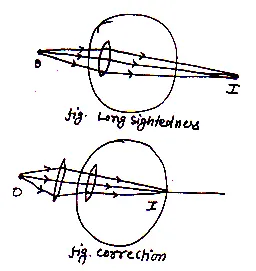
This defect arises due to increase in focal length of eye lens.
Due to decrease in size of eyeball.
Correction of Long Sightedness:
Long sightedness can be corrected using convex lens of proper focal length.
Let an object O be placed at a distance 25cm. (Least distance of distinct vision) from eye.
Therefore and
Using
We get
And power of the lens is given by
Presbyopia:
A human eye, which cannot see near objects as well as distance objects clearly us said to suffer from a defect known as presbyopia.
Cause:
This defect arises in old age due to weakness in cilliary muscles and in decrease of flexibility of the crystalline lens.
Correction:
This defect can be corrected by using bi focal lens i.e a lens that is a combination of convex and concave lens.
44 Simple Microscope or Magnifying Glass: imp
Simple microscope consists of a convex lens of small focal length.
Principle:
It is bases on the fact that when a object is placed between the centre and focus of a convex lens then virtual, erect and magnified image is formed.
Magnifying Power:
It is defined as the ratio of angle subtended by image to the angle subtended by object when both are placed at least distance of distinct vision.
As from diagram, the image is already at least distance of distinct vision and and
are the angle sustained by object and image at centre of the lens.
Then magnifying power
If are small then we may write
Now from we get
And from we get
So
Or
Now from lens formula
Multiplying both sides by
Or
But
⟹
Which is required expression for magnifiying power of a simple microscope. As f decrese then m increses i.e smaller is the focal length greater will be the magniftying power.
Uses:
It is used by studetns in science laboratories for reading vernier scale.
It is also used by jewellers and watch makers for precision work.
42Compound Microscope: m.imp
A compound microscope is used to obtain a highly magnified image of a tiny object.
Construction:
In compound microscope two lenses are held co-axial at the free ends of tube, at a suitable fixed distance from each other. The distance of objective lens from the object can be adjusted by a specific arrangement.

Magnifying Power:
It is defined as the ratio of angle subtended by the final image to the angle subtended by the object when are placed at least distance of distinct vision.
i.e
For small we may write
and
So ………(1)
Now from we get
And from
So from (1)
Now Dividing and multiplying RHS by we get
⟹ ……(2)
W
…… (3)
as and
are similar so
=
so magnifying power of objective lens
=
……..(4)
So using (3) and (4 ) in equation (2) we get
Or
As object lies very near to focal length of objective lens so we may write
And also image lies close to eye lens whose focal length is very short.
So
So
As and greater than 1 so image is inverted and enlarged.
Question: A compound microscope has a magnification of 30. The focal length of its eye piece is 5 cm. assuming the final
Image is to be formed at the least distance of distinct vision 25 cm, calculate the magnification produced by the objective.
Solution: Given, M = 30, fe = 5 cm, D = 25 cm
From
30 = 60 m0
5
Question 20. A compound microscope consists of an objective lens of focal length 2.0 cm and an eyepiece of focal length 6.25 cm separated by a distance of 15 cm. How far from the objective should an object be placed in order to obtain the final image at the least distance of distinct vision (25 cm)?
Solution: We want the final image at least distance of distinct vision. Let the object in front of objective is at distance υ0. As
so image distance of objective lens
Now we can get required position of object in point of objective.
As
So object should be 2.5 cm in front of objective lens, magnifying power may be given as
43 Telscope:
Telescope is an optical instrument to clearly observe the distant objects.
Types:
1.Refracting Type Telescope
2. Reflecting Type Telescope
Refracting Type:
(i) Astronomical Telescope
(ii) Terrestrial Telescope
Reflecting Type:
(i) Gassegrain Type
(ii) Newtonian Type
44 Astronomical Telescope: m.imp
It is an optical instrument which is used for observing distinct image of for distance apart bodies such as start planets etc.
Construction:
It consist of two lenses objective lens is of large focal length and eye lens of small focal length. These lenses are mounted co-axially at the free ends of a tube. The distance can be adjusted between these lenses. There may be two cases of image formation by astronomical telescope:
In normal adjustment of telescope, the image is formed at infinity.
As shown in fig. a parallel beam of rays coming from a object at ∞ form image at the focus of eye lens. Which is real, inverted and diminished and final image formed at ∞ which is highly magnified and is inverted w.r.t. object.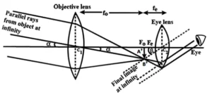
Magnified Power:
It is defined as the ratio of angle subtended by the image to the angle subtended by object at eye when both are at the least distance of distinct vision.
i.e
as angle are small
so and
from
And from
So
⟹
Or
Here sign indicate that final image is real and inverted. Hence to increase magnified power, focal length of objective lens should be large as compare to eye lens.
Astronomical Telscope when Final Image is Formed at the least Distance of Distinct Vision:
Magnifying Power:
It is defined as the ratio of angle subtended by the final image to the angle subtended by the object when both are at the least distance of distinct vision.
i.e
as are small
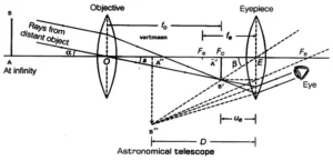
so and
⟹
From fig. in
And from
So
Here
And
Now for eye lens
Here
So
⟹
Or
Using all value in eq. (i) we get
Question 21. A small telescope has an objective lens of focal length 144 cm and an eyepiece of focal length 6.0 cm. What is the magnifying power of the telescope? What is the separation between the objective and the eyepiece?
Solution: given ,
=6cm,
As we know
And separation
45 Reflecting telescopes m.imp
Reflecting telescopes are basically of two types.
Newtonian reflecting telescope
The first reflecting telescope set up by Newton is as shown in fig.  it is consist of a large concave mirror large focal length as the objective, made of an alloy of copper and tin. A beam of light from the distant star is incident on the objective. Before the focus of the ray at the focus a plane mirror is placed at an angle 45o between the path of the ray , which reflect the rays toward the eye piece adjusted perpendicular to the axis of the instrument. The eye piece forms a highly magnified ,virtual and errect image of the distant object.
Gassegrain reflecting telescope
Gassegrain reflecting telescope is consist of a large concave mirror having a hole at centre. There is a small convex (secondary) mirror near the focus of the primary mirror. The eyepiece is placed on the axis of the telescope near the hole of the primary mirror.
The parallel rays from the distant object are reflected by the large concave mirror. Before these rays comes to focus at F, they are reflected by the small convex mirror and are converged to a point I just outside the hole.
The final image is formed at I is viewed through the eyepiece.
As the first image at F is inverted with respect to the distant object and the second image I is errect w.r.t the first image at F, hence the final image is inverted w.r.t the object.
Let fo be the focal length of the objective and fe that of the eyepiece.
For the final image formed at the list distance of the distinct vision
For the final image formed at infinity,
Advantage of the reflecting type telescope over the refracting type telescope
The image formed by reflecting type telescope is more bright
Reflecting type telescope have large resolving power.
Reflecting type telescope uses objective mirror , not a lenses so it is free from the chromatic aberration.
Reflecting type of telescope is cheap and simple to make.
1