Wave Optics
Chapter-10 Huygens Principle and Interference of Light (Wave Optics)
46 Wave Optics or Physical Optics:
According to wave nature of light, light is a form of energy which travels through a medium in the form of transverse wave motion. The speed of light in a medium depends upon the nature of the medium. Huygenberg supposed that space is also a hypothetical medium filled by aluminiferous ether which is highly elastic, low density and massless.
47 Wave Front:
A wave front is defined as the continuous locus of all the particles which are vibrating in the same phase. The particles which are at the same distance from a source of light are in same phase, the locus of such a particles called wave front.
Wave front may be three types:
Spherical Wave Front: 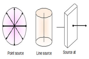
The wave front around a point source of light is called spherical wave front. As shown in fig. a.
Cylindrical Wave Front:
The wave front around a line source of light is called cylindrical wave front. As shown in fig. b.
Plane Wave Front:
When the source of light is at large distance then the infinite small part of spherical or cylindrical wave front is called plane wave front . As shown in fig. c. A ray of light always moves normally to the wave front.
48 Huygens Principles: imp
Huygens’s principle is the basis of wave nature of light. It tells that how a wave front can propagates through a medium.
It is based on the following assumptions:
There is a wave front around a source of light and every point on the wave front act as a fresh source of new disturbance, called secondary wave or wavelets.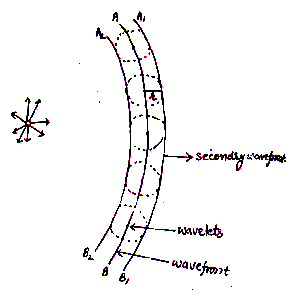
These secondary waves or wavelets spread out in all directions with speed of light.
A surface touching to these secondary wavelets in forward direction gives the new wave front called secondary wave front.
The distance travelled by a wave front in sec may be given by
Where C is the velocity of light
The wave fronts moves only in forward direction, no backward flow is possible because the resultant amplitude of all the wave fronts in backward direction is zero.
48 Laws of Reflection based on Wave Theory of Light:
Suppose AB is a incident wave front which incident on surface and reflects so that CD is the reflecting wave front.
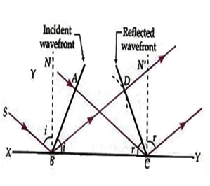
Now from Huygens principle time taken by light to reach from A to C, should be equal to time taken to reach from B to D.
Now as from diagram
In and
we have
And
Also
⟹
⟹
This is law of reflection.
49 Laws of Refraction based on Wave Theory:
Suppose AB is incident wave front, incident at refracting surface XY and reflect along CD. Again suppose that, is the velocity of light in rare medium and
is velocity of light in denser medium.
Now according to Huygens principle, the time taken by light to move from A to D is equal to time taken move from B to C.
So and
Now as from diagram, in
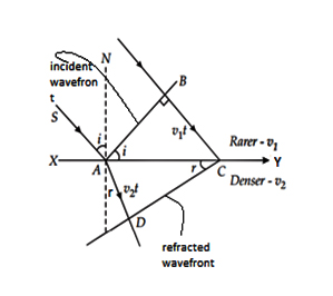
we have
And from
Dividing eq. (i) and (ii) we get
Or
Or
This is Snell’s law or law of refraction.
50 Effect on wavelength, frequency and speed during refraction of light:
As
Hence wavelength of a medium is directly proportional to phase speed and inversely proportional to its refractive index.
Also
Hence, speed of light in vacuum is larger than speed of light in medium.
Question 22: Monochromatic light of wavelength 589 nm is incident from air on a water surface. What are the wavelength, frequency and speed of
(a) reflected. (b) Refracted.
Refractive index of water is 1.33.
Answer: (a) Given a monochromatic light has a wavelength of
.
And, . Refractive index of water,
We now that the ray incident on the medium gets reflected back to the same medium therefore, We have the frequency of light is given by the relation,
(b) Given, .
Refractive index of the water
In the case of refraction, speed and wavelength will change as the medium is changing however, the frequency will remain the same because it doesn’t change when the medium is changed,
so, frequency
Speed of rays: .
Now, the Wavelength of light
=
.
Question 23: Light of wavelength 5000 Å fall on a plane reflecting surface. What are the wavelength and frequency of the reflected light? For what angle of incidence is the reflected ray normal to the incident ray?
Answer: Frequency of reflected light=
Wavelength and frequency will be the same when the ray is reflected. Hence wavelength and frequency of light is
and
respectively.
as per the law of reflection, angle of incidence is always equal to angle of reflection
.
Now, when the reflected ray is perpendicular with incidence ray,
so
Hence the angle of incidence is 45 for this condition.
51 Behavior of a Prism, Lens and Mirror:
Behavior OF Prism: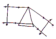
As shown in diagram a wave front AB is incidence on the prism and is its refractive wave front
. Here the ray of light from
travel large distance from ray from B to
because the ray suffer large thickness from glass slab so small distance coverage.
Behaviors of A Convex Lens: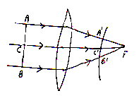
As shown in fig. AB is a incident wave front and is refracted wave front through convex lens.
Behaviors of a Concave Mirror: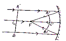
As shown in fig. AB is an incident wave front incident at C and is refracted wave front from concave mirror.
52 Principle of Superposition of Waves:
It is the phenomenon of mixing of two or more than two waves in such a way that the resultant waves have displacement or amplitude equal to vector sum of combining waves. 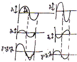
There may be two cases.
(i)When crust fall over crust and then trough fall over trough then the resultant amplitude may be given
As
(ii)When crust fall over trough or trough fall over crust then resultant amplitude is given by
53 Coherent and Incoherent Addition of light:
As electric vector is responsible for the optical effect of light, so the electric oscillation produced by two sources is given by
And
Therefore, the intensity produced by two waves is
And
Now the resultant intensity may be given as
Or average intensity of combined wave is
Where
or
Or
If frequency are same then
also for full cycle
and
⟹
=K
Or
Hence, to obtain interference of light we need two sources with same frequency and of constant phase difference such a pair of source called coherent source and resultant intensity of coherent source is
But when there are two different source then phase difference does not remains constant and for full cycle
So
In this case, interference phenomenon does not observe.
Such source of light which does not have constant phase differences, are called incoherent sources.
54 Coherent Sources: m.imp
The two sources, which have same wavelength, same frequency and same or constant phase difference, are called coherent sources.
Condition for Obtaining Two Coherent Source of Light:
The two sources should be Monochromatic.
Monochromatic source of light, the sources of light which have single wavelength is called monochromatic source.
(ii)The two coherent sources should be obtained from a single source of light by division of wave front or by division of amplitude.
(iii)The path difference between the waves from two sources must be small.
Q. Why two independent source of light cannot be coherent.
Ans. Light is emitted by an electron in atom when it comes to ground state from an excited state. As different sources may not have equal number of atoms and same excited state. Therefore, a constant phase difference cannot be occurred. So we can say that two different source of light cannot be coherent. A coherent source pair is obtained by a single source of light.
55 Interference of light: imp
It is the phenomenon of redistribution of light energy due to superposition of light waves from two coherent sources resulting dark and bright fringes.
At a point where resultant intensity is large called construction interference.
At a point where resultant intensity is small called destructive interference.
Condition for Sustained Interference of Light: imp
The two sources should be coherent.
The sources of light should be strong.
The two sources should be monochromatic.
The source should be very close to each other.
The sources should be point source.
The distance between screen and slit should be suitably adjusted.
56 Young’s Double Slit Experiment: m.imp
Young was the first to demonstrate the phenomenon of interferences of light. The experimental setup used by young is as shown in fig.
In this experiment, two coherent sources were obtained by a source of light S. 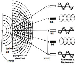
A screen is placed at a distance from the double slit. Then we get successive bright and dark fringes of same width, which were explained as.
When crust fall over the crust and trough fall over the trough then the intensity of resultant wave increase and we get bright fringes, this interference phenomenon is called constructive interference.
Now when crust fall over trough or trough fall over crust then resultant intensity decrease and we obtain dark fringes or destructive interference. From diagram we can see that the bright and dark fringe is obtains one after other and equality spaced.
57 Condition for Constructive and Destructive Interference of Light: m.imp
Let the waves from two coherent sources of light are
Where and
are the amplitudes of the waves and ∅ is the constant phase difference between them.
Now according to superposition of waves
Or
Or
Or
Let
And
So
⟹
Thus, resultant wave is harmonic wave with amplitude R.
Now squaring and adding eq. (iii) and (iv)
Or
Or
As intensity is directly proportional to square of amplitude of the waves
So
So eq. (v) may be written as
For construction interference
I should be maximum i.e
⟹
i.e where
If is the path difference then it may be given as
⟹
Hence for constructive interference phase difference or path difference should be equal to
.
For destructive interference:
I should be minimum i.e
⟹
i.e where
And corresponding path difference should be
Or
58 Interference and Energy Conservation:
In case of interference pattern, we know that
And
And
Or
Or
If there were no interference then intensity of light from two sources at every point on the screen would be
Which is same as in interference pattern. Thus interference of light obeys law of conservation of energy.
59 Expression for Fringe Width in Interference: m.imp
Or
Theory of interference of Light:
Let us suppose two coherent sources of light A, B placed d distance apart and are obtain from a single source of light. They produce central bright fringe at point C having distance D from the slit.
Now we want to obtain condition for constructive or destructive interference at point P having distance from C.
As the path difference between the rays reaching at P is
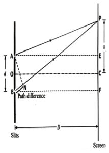
Now from we have
Again from
Subtracting eq. (ii) from (i) we get
Or
In addition, we can take
So
Or
For bright fringe or for maxima at P.
Path difference should be
For central bright fringe
For first maxima
For second maxima
Similarly for third maxima
For maxima
ii)For dark fringe or for minima
The path difference should be
For first minima
For second minima
For third minima
And for minima
Comparing the position of maxima and minima, we can see that they are situated alternatively.
Now the width of dark fringe is
⟹
Or
Similarly separations between two successive dark fringes are
Or
Hence, all dark and bright fringes are of equal length or width.
Question 24: In a Young’s double-slit experiment, the slits are separated by 0.28 mm and the screen is placed 1.4 m away. The distance between the central bright fringe and the fourth bright fringe is measured to be 1.2 cm. Determine the wavelength of light used in the experiment.
Answer: Given,
Distance between central and fourth bright fringe
And
As we know,
So
Hence wavelength of the light is 600nm
Question 25: In double-slit experiment using light of wavelength 600 nm, the angular width of a fringe formed on a distant screen is 0.1°. What is the spacing between the two slits?
Answer: Given, Wavelength of light = 600nm
Angular fringe width
m
Hence spacing required between the two slits is m
60 Fringes Shift:
It is the phenomenon of shift in the position of fringe when a transparent thin film is placed in the path of light. If a transparent sheet of refractive index and thickness
is placed in the path of light, then optical path becomes
instead of
, increasing by (
.
6() Diffraction and Polarization of Light
61 Diffraction of Light:
It is the phenomenon of bending of light around a corner of an obstacle or aperture in the path of light. According to Fresnel, diffraction occur due to interface of secondary wavelets starting from portion of the wave front, which are not blocked by the obstacle or from portion of the wave front, Narrower the slit greater is the diffraction.
62 Diffraction of Light At A Single Slit: m.imp
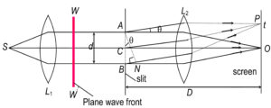
Suppose a source of light is placed at the focus of a collimating lens
, which produces a parallel beam of light. Now again suppose a wave front
incident on narrow rectangular slit
of width
.
Now according to Huygens principle, all part of slit AB becomes source of secondary wavelets, which are in same phase. These wavelets spread out in all direction and causes diffraction of light. This diffraction pattern is focused on the screen by lenses which is placed at focus of
.
Central Maxima:
All the secondary wavelets going straight across slit AB are focused at the central point O on the screen. All rays meet constructively at O and forms central maxima at O, due to constructive interference.
Calculation of Path Difference:
The path difference between the rays reaching at P from A and B is
Position of Minima:
Suppose P is located on screen having path difference and angle
then we get
We can divide slit AB into two halves AC and BC. Then path difference between the wavelets from A and C will be and is same for B to C. These wavelets from two halves AB and BC reaches the P in opposite phase. They interfere destructively so produces minima.
Thus condition for 1 dark fringe or minima is
Again condition for second dark fringe is
Hence, condition for dark fringe is
where
Position of Secondary Maxima:
Suppose P is located on screen having path difference
when
then
Here we can divide the slit into three equal parts. The path difference between two corresponding parts will be. The wavelet from these parts has minima, but the wavelet from third part we get some intensity of light so we get secondary maxima.
Thus condition for first, secondary maxima is
Similarly condition for secondary maxima is
Hence, condition for secondary maxima is
where
Intensity Distribution Curve:
If we plot a graph between the intensities of maxima and minima v/s diffraction angle then we get a graph as shown in fig. it have central maxima at
and secondary maxima at
and minima at
.
63 Width of Central Maxima: imp
The angular separation between the directions of the first minima on the two sides of central maxima is called angular width of the central maxima.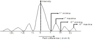
The direction of first minima on either side of central maxima is
.
So the angular width of central maxima
If D is the distance of the screen from slit then linear width of central maxima is
Question26: A slit of width 3 mm is illuminated by light of = 600 nm at normal incidence. If the distance of the
screen from the slit is 60 cm, the distance between the first order minimum on both sides of central maximum is
Solution: Given d = 3 mm = 3 10–3 m = 600 nm = 6 10–7 m, D = 60 cm = 0.60 cm
Distance of first order minima from central maximum
Distance between first order minimum on both sides of the central maximum
= 0.24 10–3 m
Question27: A beam of wavelength 6000 Å is incident on a slit of width 0.2 mm. The angular spread of the central
maximum is
Solution: Given = 6000 Å = 6000 Å = 6000 10–10 m
d = 0.2 mm = 0.2 10–3 m
Angular spread of the central maximum
radian.
Question 28: In a single slit diffraction experiment, the width of the slit is made double the original width. How does this affect the size and intensity of the central diffraction band?
Answer: width of the central diffraction band is given by where d is the width of the slit.
So when we double the width of the slit, the size of the central diffraction band reduces to half of its value. But, the light amplitude becomes double, which increase the intensity 4 times.
Question 29: A parallel beam of light of wavelength 500 nm falls on a narrow slit and the resulting diffraction pattern is observed on a screen 1 m away. It is observed that the first minimum is at a distance of 2.5 mm from the centre of the screen. Find the width of the slit.
Answer: Given
The distance of the first minimum
The wavelength of the light
Now, As we know,
Hence, the width of the slit is 0.2 mm.
64 Validity of Ray Optics: Fresnel’s Distance: m.imp
The distance at which the diffraction spread of a beam is equal to the size of the aperture is called Fresnel’s distance.
Is a screen is placed at distance D, then spreading of beam over a linear width is
When
then
⟹
⟹
If then there is no spreading of light and hence ray optics is valid up to
.
Or
or
Here is called size of Fresnel’s zone and denoted by
.
Question 30: Estimate the distance for which ray optics is good approximation for an aperture of 4 mm and wavelength 400 nm
Answer: Given Aperture
Wavelength of light
Now, Distance for which ray optics is a good called Fresnel’s distance:
Hence distance for which ray optics is a good approximation is 40m.
Question 31 : Two towers on top of two hills are 40 km apart. The line joining them passes 50 m above a hill halfway between the towers. What is the longest wavelength of radio waves, which can be sent between the towers without appreciable diffraction effects?
Answer: Given, Distance between two towers = 40km
size of aperture =
Now, As we know Fresnel’s distance is equal to half of the distance between towers
Also from the formula:
Hence this is the required longest wavelength of the radio wave, which can be sent in between the towers without considerable diffraction effect.
65 Difference between Interference and Diffraction: imp
Interference :-
1. Interference is a result of superposition of two waves starting from two different wave front of two coherent sources.
2. All bright and dark fringes are of same size.
3. All bright fringes have same intensity.
4. Region of dark fringes are perfectly dark.
Diffraction:
1. Diffraction is result of superposition of secondary waves starting from different parts of the same wavelet.
2. The width of central bright fringes is twice the width of any secondary maxima.
3. Intensity of bright fringe decrease as we move away from central bright fringe on either side.
4. Region of dark fringes are not perfectly dark.
66 Diffraction as a Limit of Resolving Power: imp
As all optical instruments such as lens, telescope, microscope etc. act as aperture. Light on passing through them undergo diffraction. This put a limit on their resolving power. Here limit of resolution and resolving power may be defined as.
Limit of Resolution:
The smallest linear or angular separation between two point objects up to which they can be seen separate is called limit of resolution.
Resolving Power:
The ability to resolve or separate the image of two nearby point objects so that they can be seen distinctly is called resolving power. It is equal to reciprocal of the limit of resolution of the optical instruments.
Smaller the limit of resolution of an optical instrument greater is its resolving power.
67 Ray Leigh Criterion for Resolving power:
According to Ray Leigh criterion, the image of two point objects is just resolved when the central maxima of one fall over the first minima of the second image.
Resolving Power of Microscope and Telescope: imp
(i)The resolving power of a microscope
It is defined as the reciprocal of the smallest distance between two point objects at which they can be just resolved when seen through the microscope.
The smallest distance between two point objects at which they can be seen just resolved by a microscope is called limit of resolution of microscopes and can be given by
⟹
Here λ is wavelength of light used and is the half of angle of cone and μ is the refractive index between the objects and microscopes. Here factor
is called numerical aperture.
(ii)Resolving Power of Telescope,
it is defined as the reciprocal of the smallest angular separation between two distant object whose image can be just resolved by it. The smallest distance between two points object at which they can be seen just resolved by a telescope is called limit of resolution of telescope.
It is
so resolving power of telescope
Here λ is wavelength of light used; D is the diameter of the telescope objective.
68 Resolving Power of Human Eye:
As diameter of pupil of human eye is about
If we take then smallest angular separation between two distant objects that a human eye can see is
Thus, human eye can see two objects having angular separation one minute. This is called limit of resolution of human eye. So resolving power for two objects having a distance of 1 Km. from eye is
or.
Thus, human eye can see two objects having 30cm separation from one kilometer.
69 Polarization or Polarization: m.imp
In ordinary light, electric field vector vibrate in all direction in a plane perpendicular to direction of light so this light is called unpolarized light for example light from sun, sodium lamp, bulb or a candle is unpolarized light. 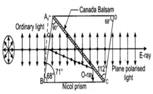
If this unpolarized light is passed through a polarizer (a device that restrict the vibration of light only in one direction) then it becomes polarized light, hence. A light having electric field vector vibrating only in one direction perpendicular to direction of propagation of light is called plane polarized light. The phenomenon of polarizing of light is called polarization.
Experiment to Demonstrate Polarization of Light:
when a unpolarized light is passed through a polarizer then it becomes plane polarized light and when again passed through a second polarizer placed parallel to first then we get same intensity of light as that of passed through first polarizer. Here second polarizer, which is used to analyses the polarized light, is called analyzer. Now if plane polarized light obtained from a polarizer is passed through a analyzer having per pending axis to that of analyzer then we obtain no any light. This shows that light obtained by a polarizer was the plane polarized light.
70 Law of Malus: m.imp
In 1809 E.N. Malus discovered that when a beam of completely plane polarized light is passed through a analyzer then the intensity I, of transmitted light varies directly to the square of cosine of angle between analyzer and polarizer. This statement is called law of Malus.
i.e
or 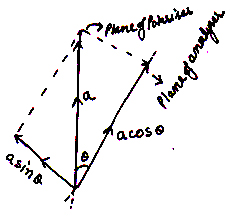
Here is the maximum intensity of transmitted light. It is approximately half the unpolarized light, which is passed through the polarizer.
Proof:
Suppose polarizer and analyzers are inclined at an angle. Let it the intensity and
is the amplitude of plane polarized light transmitted by polarizer.
Resolving in to rectangular component we get
along analyzer and
⊥ to analyzer.
So component along analyzer and only be transmitted by analyser.
So intensity of light transmitted by analyzer is
Or
Where is the maximum intensity of light transmitted by analyzer.
The above relation is called law of Malus.
When then
⟹.
Hence, we can say that when polarizer and analyzers are placed parallel to each other then maximum intensity of light is obtained.
When
Here when both are placed ⊥ to each other then we get no light.
71 Method of Producing Plane polarized Light: m.imp
A ordinary light can be polarized by:
1. Reflection
2. Scattering
3. Double Reflection
4. Selection Absorption.
Polarization by Reflection: Brewster’s Law:
According to Malus when a ordinary light is incidented on a transparent surface, then the reflected ray is plane polarized. Now the extent of polarization depends upon the angle of incident.
The angle of incident at which a beam of unpolarized light falling on a transparent surface is reflected as a beam of completely plane polarized beam is called Brewster angle. Brewster found that the polarizing angle, reflected and transmitted ray are ⊥ to each other.
Now suppose is the polarizing angle (Brewster angle) and
is the corresponding angle of refraction then,
⟹
Now from Snell’s Law
Or
Or
This relation is called Brewster’s law. According to this law, the tangent of Brewster angle of incidence is equal to relative refractive index.
The value of depends upon refracting medium and wavelength of light used.
Question 32: What is the Brewster angle for air to glass transition? (Refractive index of glass = 1.5.)
Answer: As we know where
is the polarizing angle, also called the Brewster angle.
so from here
Hence Brewster angle is.
Polarization by Scattering:
When light is incidented on small particles whose size is comparable of wavelength of light then it is absorbed by electrons and emitted in all direction, this phenomenon of light is called scattering of light. 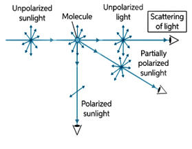
When light fall on a scattered along then we obtain plane polarized light along
and
.
Polarization of Light by Double Refraction: Nicole Prism:
Nicole Prism is a optical device made from calcite crystal for producing and detecting plane polarized light.
Construction:
Nicole Prism is consisting of two-calcite crystals whose ends are grounded away at an angle 68 and are joined with glue Canada balsam.
Action and Working:
When ordinary (unpolarized Light) passes through a calcite, crystal then it split in to two rays:
(i) Extra Ordinary Ray
(ii) Ordinary Ray.
Nicole Prism eliminates the ordinary ray by total internal reflection and allow extraordinary ray (plane-polarized ray) to pass through it. Hence, we get e-ray.
Explanation:
The refractive index of calcite crystal for ordinary and extra ordinary are 1.66 and 1.49 respectively and refractive index of Canada balsam then it suffer T.I.R. hence ordinary ray is unable to pass through Canada balsam. On the other hand, extra ordinary does not suffer TIR so we get e-ray through Nicole prism.
72 Polarizer:
A device that plane polarizes the unpolarized light by passing through it is called a polarizer.
Some commonly used Polarizer are:
(i)Tourmaline crystal:
tourmaline is so cut that its plane containing its optical axis. When unpolarized light is incidented on it then allow those light to pass through it, which have parallel to its axis.
(ii)Nicole Prism:
It consists of two-crystal cut in specific shape.
(iii)Polaroid:
Polaroid is thin commercial sheets, which are based on the property of sensitive absorption to produce an intense beam of plane polarized light.
Uses of Polaroid’s: imp
Sunglasses and Camera Filter:
Polaroid’s reduces the glare of light produced by reflection from sling surface such as water surface.
In Window Panes of Airplanes:
One of the Polaroid is fixed while the other can be rotated to control the amount of light coming in.
In photo Elasticity:
In examining plastic models and glass Polaroid’s are used www.vartmaaninstitutesirsa.com
In 3D Movies:
In 3D movies two Polaroid glass screen are used which have polarization perpendicular to each other. So one eye can see one image and other eye can see slightly different image.
In LCDS (Liquid Crystal Display), the Polaroid glass is used.
Plane of Polarization and Plane of Vibration:
Plane of Vibration:
The plane containing the direction of vibration of vibration and direction of wave propagation is called plane of vibration.
Plane of Polarization:
The plane passing through the direction of wave propagation and perpendicular to plane of vibration is called the plane of polarization. No vibration occurs in the plane of polarization.
1