Unit-4(b)Alternating Current
13. Alternating Current:
A current whose magnitude changes continuously w.r.t. time and direction reverses continuously or periodically called A.C. current.
It may be represented as![]()
Here ![]() is the instantaneous value of A.C. and
is the instantaneous value of A.C. and ![]() is maximum value of AC also called peak value and
is maximum value of AC also called peak value and ![]() is phase angle, where
is phase angle, where ![]() is called angular frequency.
is called angular frequency.
As![]()
Here T is time period of AC and ![]() is its frequency.
is its frequency.
Similarly![]() of AC may be given as
of AC may be given as![]()
Amplitude:
The maximum value attained by A.C. called amplitude; it is also called peak value of AC and represented as ![]()
Time Period:
The time taken by alternating current to complete one cycle is called its time period. It is denoted by T.![]()
![]()
Frequency:
The number of cycle passing per second of A.C. is called its frequency.
It is denoted by ![]()
The frequency of A.C. in our houses is![]() .
.
14. Mean or Average Value of A.C.: M.Imp
It is defined as that value of D.C. which would send the same amount of charge in a circuit in the same time as is sent by the A.C. in its half cycle. It is denoted by ![]() or
or![]() .
.
As we know![]()
Now suppose ![]() is the amount of charge sent in time
is the amount of charge sent in time ![]() such that
such that
![]()
For total charge sent in half cycle, integrate both sides we get
![]()
Or ![]()
![]()
![]()
![]()
![]()
![]()
![]()
If ![]() represent the mean value or average value of AC in half cycle
represent the mean value or average value of AC in half cycle
Then ![]()
Comparing eq. (i) and (ii)
![]()
![]()
Or ![]()
Hence mean value or average value AC is 0.637 times to its peak value.
15 Mean value or average value of alternating emf :
It is defined as that value of steady ![]() which would send the same amount of charge in a circuit in the same time as is sent by alternating
which would send the same amount of charge in a circuit in the same time as is sent by alternating ![]() in its half cycle. It is denoted by
in its half cycle. It is denoted by ![]()
As we know alternating ![]() can be represented as
can be represented as
![]()
Or ![]()
Or ![]()
Or ![]()
or ![]()
Total charge sent by alternating ![]() in half cycle is
in half cycle is
![]()
![]()
![]()
![]()
![]()
![]()
![]()
If ![]() is the mean or average value of alternating
is the mean or average value of alternating ![]() over half cycle
over half cycle
Then![]()
Comparing eq. (i) and (ii)
![]()
Hence mean value or average of alternating ![]() is 0.637 time its peak value.
is 0.637 time its peak value.
16 Root mean square value of alternating current: M.Imp
It is defined as that value of direct current which would produce the same amount of that in a given resistance in same time as is produced by AC when passed through same resistance in same time.
As the instantaneous value of current may be given as
![]()
The amount of heat produced in the resistance by this current in time ![]() is
is
![]()
That total heat produced in one cycle is
![]()
or ![]()
![]()
![]()
![]()
![]()
![]()
![]()
![]()
If ![]()
![]()
Comparing eq. (i) and (ii)
![]()
Hence ![]() value of AC is equal to 0.703 time its peak value.
value of AC is equal to 0.703 time its peak value.
17. Root mean square value of alternating emf or effective value of emf:-
It is defined as that value of a steady ![]() which would produce the same amount of heat in a resistance as is produced by the given alternating
which would produce the same amount of heat in a resistance as is produced by the given alternating ![]() when applied on the same resistance in same time. Suppose instantaneous value of alternating
when applied on the same resistance in same time. Suppose instantaneous value of alternating ![]() is
is
![]()
Now suppose ![]() is the small amount of that generated in small time
is the small amount of that generated in small time ![]() as
as
![]()
![]()
Now total heat generated in complete cycle is
![]()
![]()
![]() (
(![]() )
)
Or ![]()
If ![]() is the
is the ![]() value of
value of ![]() then heat produced in T time is
then heat produced in T time is
![]()
Comparing eq. (i) and (ii)
![]()
Or ![]()
Or![]()
Or ![]()
Hence effective ![]() or root mean square value of
or root mean square value of ![]() is equal to 0.707 times to the peak value of
is equal to 0.707 times to the peak value of ![]()
From average value of ![]() value of
value of ![]() we can see that
we can see that ![]() value of current is larger than average value of
value of current is larger than average value of ![]()
Question10: If the voltage (in volts) in an ac circuit is represented by the equation, V = 220![]() sin (314 t – ),(where t is in seconds)Calculate (a) peak and rms value of the voltage (b) frequency of ac.
sin (314 t – ),(where t is in seconds)Calculate (a) peak and rms value of the voltage (b) frequency of ac.
Solution: (a) For ac voltage, V = V0 sin (t – ).
The peak value V0 = 220 ![]() = 311 V ,
= 311 V ,
The rms value of voltage Vrms = ![]() ; Vrms = 220 V
; Vrms = 220 V
(b) As = 2f, 2f = 314 i.e., f =![]() = 50 Hz
= 50 Hz
Example11:an electric heater draws 2.5 a current from a 220-V, 60-Hz power supply. Find
(a) The average current (b) the average of the square of the current
(c) The current amplitude (d) the supply voltage amplitude
Sol: In AC circuit, the average value of current over a long time interval is zero but ![]() is not zero. The r.m.s. value of current and voltage is given by
is not zero. The r.m.s. value of current and voltage is given by ![]()
(a) The average of sinusoidal AC values over any whole number of cycles is zero.
(b) RMS value of current
![]() so,
so, ![]()
(c) ![]() So, current amplitude
So, current amplitude
![]()
(d) ![]()
So, supply voltage amplitude ![]()
Example12.A light bulb is rated at 100W for a 220 V supply. Find (a) the resistance of the bulb; (b) the peak voltage of the source; and (c) the rms current through the bulb.
Solution (a) we are given P = 100 W and V = 220 V.
The resistance of the bulb is ![]() Ω
Ω
(b) The peak voltage of the source is ![]()
(c) Since, ![]()
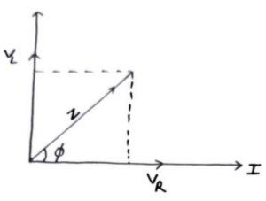
18 PhasorDiagram:
 A rotating vector that represents the sinusoidal Variation of a physical quantity is called phasor. In phasor diagram the length of the vector represents peak value of
 ![]() and the projection of this vector on any axis gives the instantaneous value of current and
and the projection of this vector on any axis gives the instantaneous value of current and![]() . The angle between this vector and
. The angle between this vector and ![]() axis gives the phase angle. The difference in angle of
axis gives the phase angle. The difference in angle of ![]() vector and current vector is called phase difference.
vector and current vector is called phase difference.
19 A.C. Circuit Containing Resistance Only: Imp
Suppose a resistance ![]() is connected to a alternating source of
is connected to a alternating source of ![]()
![]()
Again suppose that I is the amount of current flows through the resistance due to this ![]() such that
such that
![]()
Or![]()
Comparing with
![]()
We can see that
![]()
Also on comparing eq. (i) and (ii) we see that both current and ![]() are in same phase. The phasor diagram of current and
are in same phase. The phasor diagram of current and ![]() is as shown in fig.
is as shown in fig.
20 A.C. Circuit Containing Inductance Only:Imp
 Suppose a indicator L is connected to a alternating source of
 ![]()
![]()
Due to this ![]() suppose
suppose ![]() is the rate of change of current in inductor of inductance L then
is the rate of change of current in inductor of inductance L then ![]() induced in circuit is
induced in circuit is
![]()
Or ![]()
Integrating both sides we get
![]()
![]()
Or![]()
![]()
Comparing with ![]()
we get![]()
Here ![]() has same unit as that of resistance so
has same unit as that of resistance so ![]() is called inductive resistance.
is called inductive resistance.
Also comparing eq. (i) and (ii) we can see that current legs behind the ![]() by phase angle
by phase angle ![]() the phase diagram of A.C. circuit containing inductance only is as shown in fig.
the phase diagram of A.C. circuit containing inductance only is as shown in fig.
Example13. A pure inductor of 25.0 mH is connected to a source of 220 V. Find the inductive reactance and rms current in the circuit if the frequency of the source is 50 Hz.
Solution the inductive reactance, ![]()
the rms current in the circuit is ![]()
21 A.C. Circuit Containing Capacitance Only:Imp
Suppose a capacitor C is connected to a alternating source of ![]()
![]()
 Suppose due to this
 ![]() is the amount of charge stored in the capacitor of capacitance C as
is the amount of charge stored in the capacitor of capacitance C as![]()
Or![]()
Differentiating both sides, we get
![]()
Or![]()
Or ![]()
Comparing with ![]() we get
we get![]()
Here the unit of ![]() must be same to as that of resistance, so
must be same to as that of resistance, so ![]() is called capacitive resistance. Also comparing eq. (i) and (ii) we can see that current leads the
is called capacitive resistance. Also comparing eq. (i) and (ii) we can see that current leads the ![]() by phase angle
by phase angle ![]() the phasor diagram for A.C. circuit containing capacitance only is as shown in fig.
the phasor diagram for A.C. circuit containing capacitance only is as shown in fig.
Example14. a 15.0 μF capacitor is connected to a 220 V, 50 Hz source. Find the capacitive reactance and the current (rms and peak) in the circuit. If the frequency is doubled, what happens to the capacitive reactance and the current?
Solution The capacitive reactance is ![]() Ω
Ω
The rms current is ![]() the peak current is
the peak current is ![]() =1.47A
=1.47A
This current oscillates between +1.47A and –1.47 A, and is ahead of the voltage by π/2. If the frequency is doubled, the capacitive reactance is halved and consequently, the current is doubled.
22. A.C. Circuit Containing Resistance, Inductance and Capacitance in Series or (RLC Circuit): M.Imp
In it a pure resistance R, a pure inductance ![]() pure capacitor
pure capacitor ![]() are connected in series to a alternating source of
are connected in series to a alternating source of ![]() having current
having current
![]() ………………(i)
………………(i)
As we know that the voltage across resistance is in same phase with current and lags behind in case of capacitor and leads in case of inductor. The phase relationship between ![]() and current is as shown in fig.
and current is as shown in fig.
As from diagram ![]() and
and ![]() are in opposite direction so net result is
are in opposite direction so net result is ![]() along
along ![]() then resultant
then resultant ![]() of circuit can be given by
of circuit can be given by
![]()
Here![]()
![]()
![]()
![]()
![]()
Using in eq. (ii) we get
![]()
Or![]()
OrZ![]()
Here Z is total effective resistance of the circuit called impedance of the circuit.
As from diagram we may see that voltage leads the current by phase angle ![]() as
as ![]()
And direction can be given as![]() or
or![]()
When ![]() than
than ![]() i.e. the phase angle between
i.e. the phase angle between ![]() and current is zero so circuit behave as non inductive.
and current is zero so circuit behave as non inductive.
When ![]() than
than![]() , hence voltage leads the current so circuit is inductance dominated circuit.
, hence voltage leads the current so circuit is inductance dominated circuit.
When ![]() than
than![]() , therefore,
, therefore, ![]() is negative hence voltage legs behind the current. So circuit is capacitance dominated circuit.
is negative hence voltage legs behind the current. So circuit is capacitance dominated circuit.
Question15: An alternating voltage of 100 volt r.m.s. at a frequency of 400/ cycles/second is supplied to a circuit containing a pure inductance of 0.01 H and a pure resistance of 6 ohms in series. Calculate (i) the current, (ii) potential difference across the resistance, (iii) potential difference across the inductance.
Solution: The impedance of L-R series circuit is given by Z = [R2 + (L)2 ]1/2 = [(R)2 + (2fL)2] 1/2 = 10
(i) R.M.S. value of current Irms =![]() 10 amp
10 amp
(ii) The potential difference across the resistance is given by VR = Irms × R = 60 V
- Potential difference across inductance is given by VL = Irms × (L) = 80 V
Question16: A resistor of resistance R, an inductor of inductance L and a capacitor of capacitance C all are connected in series with an a.c. supply. The resistance of R is 16 ohm and for a given frequency, the inductive reactance of L is 24 ohm and capacitive reactance of C is 12 ohm. If the current in the circuit is 5 amp., find
(a) the potential difference across R, L and C(b) the impedance of the circuit (c) the voltage of a.c. supply
Solution:(a) Potential difference across resistance VR = iR = 5 × 16 = 80 volt
Potential difference across inductance VL = i × (L) = 5 × 24 = 120 volt
Potential difference across condenserVC = i × (1/C) = 5 × 12 = 60 volt
(b) Z =  =
= ![]() = 20 ohm
= 20 ohm
(c) The voltage of a.c. supply is given by v = iZ = 5 × 20 = 100 volt
23. Impedance Triangle:
A triangle formed by the three phasor ![]() is called phasor diagram. The base of triangle represents
is called phasor diagram. The base of triangle represents ![]() resistance
resistance![]() , the
, the ![]() represents reactance
represents reactance ![]() and the resultant diagram of represents impedance (Z) of the
and the resultant diagram of represents impedance (Z) of the ![]() circuit as
circuit as ![]() .
. 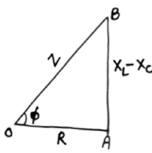
And the angle between ![]() is
is![]()
Represent that resultant of ![]() circuit
circuit ![]() leads current by phase angle
leads current by phase angle ![]()
Here the reciprocal of reactance is called susceptance of ![]() circuit and
circuit and
Reciprocal of impedance is called admittance.
Both have unit ![]()
24. AC Circuit containing Resistance and Inductance:
Let a resistance ![]() inductor
inductor ![]() is connected to a external alternating source of
is connected to a external alternating source of ![]()
As we know in case of resistance voltage and current are in same phase and in case of inductance, voltage leads current by phase angle ![]() so impedance of the circuit is
so impedance of the circuit is
![]()
And the phase angle between resultant ![]() and current is
and current is
![]()
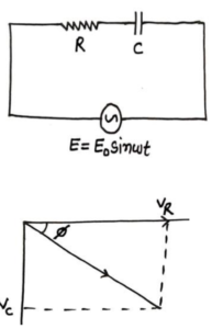
25. AC Circuit Containing Resistance and Capacitance:
Suppose a circuit in which a resistance ![]() capacitor
capacitor ![]() are connect to a alternating source of
are connect to a alternating source of ![]()
As in case of resistance the phase difference between current and ![]() is zero and in case of capacitor, voltage legs behind the current by
is zero and in case of capacitor, voltage legs behind the current by ![]() so the impedance of circuit is
so the impedance of circuit is
![]()
And phase angle between resultant ![]() and
and![]()
Example17. a resistor of 200 Ω and a capacitor of 15.0 μF are connected in series to a 220 V, 50 Hz ac source. (a) Calculate the current in the circuit; Solution (a) In order to calculate the current, we need the impedance of the circuit.
It is![]() or
or![]() Ω
Ω
Therefore, the current in the circuit is ![]() 0.755 A
0.755 A
26. Electric Resonance: or series Resonance M.Imp
A circuit in which ![]() are connected in series and the circuit admit the maximum current to a given frequency of
are connected in series and the circuit admit the maximum current to a given frequency of ![]() is called series resonant circuit.
is called series resonant circuit.
As we know the impedance of ![]() circuit is
circuit is![]()
Or![]()
Suppose for a particular value of ![]() we have
we have![]()
Or![]()
![]()
Or![]()
![]()
![]()
Or![]()
At this particular value of ![]()
![]()
![]()
So the current of the circuit is maximum i.e. ![]() .
.
The frequency ![]() at which current becomes maximum, is called series resonant frequency or natural frequency.
at which current becomes maximum, is called series resonant frequency or natural frequency.
The variation of current with frequency is as shown in fig. it is clear that when the frequency is less than or greater than resonant frequency is equal to ![]() then current is maximum. Also greater is the resistance
then current is maximum. Also greater is the resistance ![]() of the circuit small is the peak value of current.
of the circuit small is the peak value of current.
Electric resonant is also called accepter circuit as it allows the maximum current to pass through the circuit.
Q. 18How series resonant is helpful in radio and TV receiver.
The antenna of a radio/T.V. receive signal from many stations. To receive a particular signal, we tune the capacitance of the receiver, and then at a specific value, the resonant frequency of receiver becomes equal to the frequency of desired station, so resonance occurs and we have maximum current for that signal so we can see or hear that channel or signal.
27. Quality factor or Q -Factor of resonant circuit or Sharpness of resonance: Imp
The quality factor of series resonant circuit may be defined at the ratio of voltage developed across capacitor or inductor to the voltage applied across the resistance.
![]()
Or![]()
As![]() we get
we get![]()
Or![]()
Q factor is unit less.
Larger the Q factor narrower and sharper is the resonance.
28. Parallel Resonant Circuit: M.Imp
Suppose an Inductor L and Capacitor C is connected in parallel and to an external alternating source of ![]()
![]()
Again as we know in case of inductor, current legs behind ![]() by
by ![]()
So![]()
And in case of capacitor current leads ![]() by
by ![]() as
as
![]() …………(3)
…………(3)
So total current ![]()
Or![]()
Or![]()
Or![]()
When ![]() then
then ![]()
Or![]()
Or![]()
Or2![]()
Or![]()
Hence the frequency when an inductor and a capacitor are connected in parallel, the current in the circuit becomes zero called parallel resonant frequency.
The impedance of a parallel resonant circuit is maximum
The parallel resonant circuit is used in transmitting circuits. They reject the current of parallel resonant frequency and allow other frequencies/current through it. So it is also known as filter circuit or rejecter circuits or anti resonant circuit.
Example19. A sinusoidal voltage of peak value 283 V and frequency 50 Hz is applied to a series LCR circuit in whichR = 3 Ω, L = 25.48 mH, and C = 796 μF. Find (a) the impedance of the circuit; (b) the phase difference between the voltage across the source and the current; (c) the power dissipated in the circuit; and (d) the power factor.
Solution (a) To find the impedance of the circuit, we first calculate XL and XC. As
![]()
![]()
![]() Therefore,
Therefore,![]() 5 Ω
5 Ω
(b) Phase difference, φ = ![]() 53.1° Since φ is negative, the current in the circuitacross the source.
53.1° Since φ is negative, the current in the circuitacross the source.
(c) The power dissipated in the circuit is ![]()
(d) Power factor = cos φ=cos53.1°= 0.6
Example20. Suppose the frequency of the source in the previous example can be varied. (a) What is the frequency of the source at which resonance occurs? (b) Calculate the impedance, the current, and the power dissipated at the resonant condition.
Solution (a) the frequency at which the resonance occurs is ![]()
And ![]() 35.4Hz
35.4Hz
(b) The impedance Z at resonant condition is equal to the resistance: ![]()
The rms current at resonance is ![]() 66.7A
66.7A
The power dissipated at resonance is![]() 13.35 kW you can see that in the present case, power dissipated
13.35 kW you can see that in the present case, power dissipated
At resonance is more than the power dissipated in previous example.
29. Energy stored in an inductor:
Suppose a.c. is applied at an inductor of inductance L then ![]() induced in it is
induced in it is![]()
This induced ![]() will oppose the flow of current, so work is to be done against
will oppose the flow of current, so work is to be done against ![]() to flow current as
to flow current as![]()
Or![]()
Or![]()
Total amount of work done can be given as![]() Or
Or![]()
This work will store in form of energy in inductor, so energy stored in an inductor is![]()
Example21. Calculate the energy stored in an inductor of inductance 50 mH when a current of 2.0 A is passed through it.
Sol: In LR circuit, magnetic energy is stored in inductor is ![]() =0.10J
=0.10J
Example22.What inductance would be needed to store 1.0 kWh of energy in a coil carrying a 200A current?
![]()
Sol: In LR circuit, magnetic energy stored in inductor is ![]()
We have, i=200 A and ![]() Using formula of energy we get
Using formula of energy we get ![]()
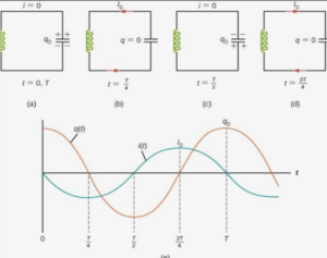
30. LC Oscillation: Imp
Suppose a circuit in which a capacitor C is connected to a inductor L through a key ![]() and the capacitor C is connected to a cell through key
and the capacitor C is connected to a cell through key ![]()
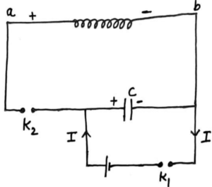
When key ![]() is closed then capacitor starts charging and store energy
is closed then capacitor starts charging and store energy![]() . Now when capacitor starts discharging through inductor
. Now when capacitor starts discharging through inductor ![]() induced
induced ![]() develop in the inductor in opposite to direction of flow of current. When capacitor is fully discharge then energy stored in inductor is
develop in the inductor in opposite to direction of flow of current. When capacitor is fully discharge then energy stored in inductor is ![]()
When inductor is fully charged then it starts discharging and capacitor starts charging in opposite direction. Now again when capacitor is fully charged then it starts discharging across L. this process is repeated again and again. It there is no any resistance in the circuit then there is resistance in the circuit then there any resistance in the circuit then there is no lose of energy then oscillation is undamped oscillation. But if there is resistance in the circuit then there is lose of energy in each oscillation so oscillation is damped.
To make a damped oscillation to undamped then a constant energy must be supplied to capacitor equal to lose of energy due to resistance continuously. The eight stage of LC oscillation are as given below.
The Frequency of Electrical Oscillator:
In LC oscillator when capacitor discharge then inductor start charging the equation of induced ![]() in inductor at any time
in inductor at any time ![]() is
is
![]()
As ![]() decrease,
decrease, ![]() increases, therefore
increases, therefore
![]()
So the eq. becomes
![]()
Or![]()
This eq. is similar to eq. of simple harmonic oscillator of frequency ![]() as
as
![]()
Comparing eq. we get
![]()
⟹![]()
Or ![]()
⟹![]()
This is the expression for frequency of ![]() oscillation.
oscillation.
31. Average Power associated with resistance or non inductive circuit: M.Imp
As we know in case of AC circuit containing resistance only, the current and ![]() are in same phase and the instantaneous value of
are in same phase and the instantaneous value of ![]() are as
are as
![]()
And![]()
So the instantaneous power can be given as
![]()
Now small amount of work done to maintain current in circuit is
Or ![]()
Or ![]()
Total work done to maintain current in full cycle is
![]()
![]()
![]()
![]()
Or ![]()
Or ![]()
Hence average power over a complete cycle of a.c. circuit containing resistance only is equal to product of virtual current and virtual ![]()
32. Average Power associated with an inductor: M.Imp
As we know in case of a.c. circuit containing inductor only, the current les behind the![]() . The instantaneous value of current and
. The instantaneous value of current and ![]() can be given as
can be given as
![]()
![]()
Mathematically work done in one complete cycle is
![]()
Or![]()
![]()
![]()
![]()
![]()
![]()
![]()
Hence average power associated with an ideal inductor is zero.
33. Average power Associated with capacitor: M.Imp
As we know in case of a.c. circuit containing capacitor only, current leads the ![]() by phase
by phase ![]() the instantaneous value of current and
the instantaneous value of current and ![]() can be given as
can be given as
![]()
And![]()
The total work done in a complete cycle is
![]()
![]()
=![]()
![]()
![]()
Hence average power associated with a capacitor is also zero. The energy supplied to build up current is returned back during discharging of the capacitor.
34 . Average Power in RLC Circuit or Inductive Circuit: M.Imp
Suppose in case of RLC circuit the current legs behind the ![]() by phase difference
by phase difference ![]() the instantaneous value of current and
the instantaneous value of current and ![]() can be given as
can be given as
![]()
![]()
Now total work done in complete cycle may be given by
![]()
Or![]()
![]()
![]()
![]()
![]()
![]()
![]()
Or![]() Or
Or![]()
Hence average power associated with ![]() circuit is equal to product of virtual current and virtual
circuit is equal to product of virtual current and virtual ![]() and cosine of angle between them.
and cosine of angle between them.
35. Power Factor of an AC circuit:
As we know power associated with an inductive circuit is
![]()
Here P is called true power, ![]() called apparent power and
called apparent power and ![]() is called power factor.
is called power factor.
Hence power factor may be defined as the ratio of true power to the apparent power.
i.e. ![]()
Now from impedance triangle ![]()
In non inductive circuit ![]()
![]()
But as power associated with a pure capacitor or pure inductor is zero
![]()
As ![]()
Hence the current through ![]() which consume no current for it maintained is called wattles current.
which consume no current for it maintained is called wattles current.
Question23: A series LCR with R = 20 , L = 1.5 H and C = 35 F is connected to a variable frequency 200 V a.c. supply. When the frequency of the supply equals the natural frequency of the circuit. What is the average power transferred to the circuit in one complete cycle?
Solution: When the frequency of the supply equals the natural frequency of the circuit, resonance occurs.
Z = R = 20 ohm. irms = ![]()
Average power transferred/cycle
P = Erms irms cos0° = 200 × 10 × 1 = 2000 watt
36. Wattles Current or IDLE Current:Imp
The current which consume no any power for its maintenance in the circuit is called wattles current.
As we know power associated with inductive circuit is![]()
![]()
Now resolve ![]() into components
into components ![]() along
along ![]()
As phase difference between ![]() is zero so power associated with
is zero so power associated with ![]() is
is
![]() ……(1)
……(1)
Again the phase difference between ![]() and
and ![]() is
is ![]() so power associated with
so power associated with ![]() is
is
![]() ……………(2)
……………(2)
Thus the component ![]() consume zero power for it’s maintains so it is called wattles current or idle current.
consume zero power for it’s maintains so it is called wattles current or idle current.
Illustration 24: When a voltage ![]() is applied to an AC circuit, the current in the circuit is found to be
is applied to an AC circuit, the current in the circuit is found to be ![]() then average power consumed in the circuit is
then average power consumed in the circuit is ![]()
Sol: Power in any AC circuit is calculated as
![]()
37. Real Resistor, Inductor and Capacitor:
In practice we cannot construct real resistor, inductor or capacitor e.g. a resistance will have little inductance due to magnetic field around it which is produced due to passes of current through it also may have some capacitance due to two conductors circuit.
Similarly inductor is also formed of wires which may have small resistance or capacitance between two turns of the coil. Again real capacitor is also not possible as it have high resistance between the plates and may have little inductance.
38. Advantage and Draw Back of AC Over DC:Imp
Advantage of AC:
- It can be transmitted to a long distance.
- It can be easily changed using transformer.
- It can be easily changed into D.C.
- Its magnitude can be easily changed using chock coil.
- It is easy and cheaper to generate.
Drawback of A.C.:
- It is more dangerous to work with AC then DC.
- The shock of AC is attractive whereas that of DC is repulsive.
- Several insulated wires are required to transmit AC.
AC can be converted into DC by rectifier and DC can be converted into AC by inverter.
Unit-4(C) Electrical Devices
39 AC Generator or AC Dynamo: M.Imp
It is a device which converts mechanical energy into electrical energy.
Principle:
It is based on the phenomenon of electromagnetic i.e. whenever amount of magnetic flux linked with the coil, and ![]() is induced in the coil.
is induced in the coil.
Constructions:
The main parts of a AC generator are as shown in fig.
- Armature:-
A rectangular coil ABCD consist of large number of turn of insulated copper wire wounded over a soft core rotating at central axis called armature.
- Field Magnet:-
A north and south pole of strong electromagnet is fixed ![]() to armature. It is of order of 1 to 2 Tesla.
to armature. It is of order of 1 to 2 Tesla.
- Slip Rings:-
![]() Are two hollow metallic rings, to which two ends of armature coil are connected. These rings rotate with the rotation of coils.
Are two hollow metallic rings, to which two ends of armature coil are connected. These rings rotate with the rotation of coils.

Brushes:-
These are two flexible metal plates of carbon rod which are kept in light contact with ![]() the purpose of brushes is to pass current from coil to external load resistance R.
the purpose of brushes is to pass current from coil to external load resistance R.
Theory and Working:
When armature coil is rotated in the magnetic field, then angle ![]() between the field and normal to the coil changes continuously due to which magnetic flux linked with the coil changes continuously and induce
between the field and normal to the coil changes continuously due to which magnetic flux linked with the coil changes continuously and induce![]() in the coil which can be given by
in the coil which can be given by
![]()
or![]()
Or![]()
![]()
![]()
Then ![]()
So from above equation ![]()
And the current produced in generator is
![]()
or ![]()
Hence mechanical energy is converted into electrical energy
Multiphase AC Generator:
- Two Phase AC Generator:
In this generator, there are two armature coil held perpendicular to each other each having their own split rings. When induced ![]() is maximum in one coil then it is minimum in other coil. The phase difference between then is
is maximum in one coil then it is minimum in other coil. The phase difference between then is ![]()
- Three Phase AC Generator:
In this generator, there are three armature coil held at ![]() to each other having their own split rings. The induced
to each other having their own split rings. The induced ![]() in each coil have
in each coil have ![]() phase difference with each other.
phase difference with each other.
In India three phase AC generator is used be cause
- Output of this is constant.
- Output is greater than other two.
- This system is more economic.
In India the frequency of rotation is ![]() and USA frequency of rotation is
and USA frequency of rotation is ![]()
Example25. Kamla peddles a stationary bicycle the pedals of the bicycle are attached to a 100 turn coil of area 0.10 m2
. The coil rotates at half a revolution per second and it is placed in a uniform magnetic field of 0.01 T perpendiculars to the axis of rotation of the coil. What is the maximum voltage generated in the coil?
Solution Here f = 0.5 Hz; N =100, A = 0.1 m2 and B = 0.01 T.
Employing eq.![]()
![]()
The maximum voltage is 0.3 14 V. We urge you to explore such alternative possibilities for power generation.
40. Transformer: M.Imp
It is a device which is used for changing the magnitude of AC voltage or ac current. It is of two types.
- Step up transformer:
A transformer which increases the AC voltage is called step up transformer.
- Step down Transformer:
A transformer which decreases the AC voltage called step down transformer.
Principle:
 It is based on the principle of mutual induction i.e. when the amount of magnetic flux linked with a coil changes then
 ![]() is induced in the neighboring coil.
is induced in the neighboring coil.
Construction:
A transformer is consisting of a rectangular soft iron core made in form of laminated sheets insulated from each other.
Two coils ![]() and
and ![]() are well insulated from each other and also insulated from iron core. In step up transformer number of turn in
are well insulated from each other and also insulated from iron core. In step up transformer number of turn in ![]() is larger then
is larger then ![]()
Theory and working:
According to frequency law the ![]() induced per unit turn
induced per unit turn ![]() is same for both coils. If
is same for both coils. If ![]() are the number of turns in primary and secondary coils.
are the number of turns in primary and secondary coils.
Then![]()
![]()
![]()
Hence if ![]() then
then ![]() i.e. transformer will be step up transformer
i.e. transformer will be step up transformer
And if ![]() then
then ![]() so transformer will be step down transformer.
so transformer will be step down transformer.
Here ![]() is called transformer ratio.
is called transformer ratio.
The eq. (i) based on the assumption that
- The primary resistance and current are small.
- Both the coils are linked with same magnetic flux.
- The secondary current is small.
As if we assume that there is no energy lose in transformer then
![]()
![]()
![]()
![]()
![]()
![]()
For a step up transformer
![]() i.e.
i.e. ![]() increases and current decreases in same ratio.
increases and current decreases in same ratio.
For a step down transformer
![]() i.e.
i.e. ![]() decreases and current increases in same ratio.
decreases and current increases in same ratio.
Also![]()
Or![]()
![]()
![]()
Here let ![]()
⟹ ![]()
![]() Is the value of load resistance to which transformer is connected .
Is the value of load resistance to which transformer is connected .
Efficiency:
It is defined as the ratio of output to the input power.
![]()
For ideal transformer i.e. having no energy lose has 100% efficiency. But in practice efficiency is less than 100% due to various loses of energy in it.
41. Energy Loses in Transformer: M.Imp
- Copper Lose:-
Due to Joules heating effect there is lose of energy in form of heat in copper coils used in transformer.
- Iron Loss:
There is loses of energy due to eddy current in transformer core.
- Leakage of magnetic flux in spite of best insulation.
- Hysteresis Lose:
Due to magnetization and demagnetization of iron core, there occurs lose of energy.
- Magnetostriction:
Lose of energy due to humming noise of a transformer.
So the output power of a best transformer is roughly 90% of its input.
42. Use of Transformer:
A transformer is used in almost all AC operations e.g.
- Voltage regulator in T.V., refrigerator, computer, air conditioner etc.
- Step down transformer is used in welding purpose.
- Transformer is also used in transmission of power over a long distance.
A step up transformer is used at power station.
SOME IMPORTANT MCQ
Q.1 Magnetic flux through a surface is independent of
(a) Area of surface (b) Strength of magnetic field
(c) Shape of surface (d) angle b/w area vector of surface and magnetic field
Q.2 c.g.s. unit of magnetic flux is
(a) Weber (b) Tesla (c) Maxwell (d) volt-sec
Q.3 One Weber is equal to
(a) ![]() (b)
(b) ![]() (c)
(c) ![]() (d)
(d) ![]()
Q.4 which of the following is not equal to Weber
(a) joule/ampere (b) ![]() (c) joule-sec/coulomb d) volt/sec
(c) joule-sec/coulomb d) volt/sec
Q.5 The cause of induced emf is
- magnetic flux (b) magnetic field (c) area (d) change in magnetic flux
Q.6 The magnetic flux linked with the coil is related to number of turn N of the coil as
(a)![]() (b)
(b)![]() (c)
(c)![]() (d)
(d)![]()
Q.7 With increase in number of turn of coil induced emf in the coil
(a) Increase (b) decrease (c) remain same (d) none of these
Q.8 Polarity of induced emf is given by
(a) Faraday’s law (b) Ampere’s law (c) Lenz’s law (d) Biot’savrat’s law
Q.9 A coil is in the magnetic field then emf can be induced by
(a) By Changing magnitude of B (b) By changing area A of coil
(c) By changing orientation of coil w.r.t to B (d) all of above
Q.10 Lenz’s law is a consequence of the law of conservation of
(a) Charge (b) mass (c) energy (d) momentum
Q.11 The laws of E.M.I. have been used in the construction of a
(a) Galvanometer (b) voltmeter (c) electric motor (d) generator
Q.12 Direction of current induced in a conductor moving in a magnetic field is given by
(a) Fleming’s left hand rule (b) Fleming’s right hand rule (c) Ampere rule (d) Right hand thumb rule
Q.13 Which one is not an application of eddy current
(a) Magnetic brakes (b) speedometer (c) induction furnace (d) transformer
Q.14 The self-inductance of a coil is a measure of
(a) Electrical inertia (b) electrical friction (c) induced emf (d) induced current
Q.15 out of following, choose the correct relation
(a) 1 henry=1volt/1ampere (b) 1 henry=1ampere/1volt
(c) 1henery=1volt/1ampere/sec (d) 1 henery=1volt/1ampere-sec
Q.16 The self inductance associated with a coil is independent of
(a) Time (b) induced voltage (c) current (d) resistance of a coil
Q.17 When rate of change of current through the coil is unity, the induced emf is equal to
(a) Number of turns in the coil (b) coefficient of self inductance
(c) Total flux linked with coil (d) none of above
Q.18 Coefficient of self inductance of coil depends on
(a) Number of turns (c) area of cross section
(c) nature of material on which coil is wounded (d) all of above
Q.19 r.m.s. value of alternating current is –
(A) ![]() (b)
(b) ![]() (c)
(c) ![]() (d)
(d) ![]()
Q.20 In a purely inductive AC circuit
(a) Current leads voltage by phase angle π/2 (b) current legs behind voltage by phase angle π/2
(c) Current and voltage are in same phase (d) voltage legs behind current by phase angle π/2
Q.21 In an AC circuit containing capacitance only
(a) Current leads voltage by angle π/2 (b) voltage leads current by angle π/2
(c) Current and voltage are in same phase (d) current legs behind voltage by angle π/2
Q.22In a pure inductive circuit it the frequency of AC source is doubled, then its inductive reactance will be
(a) Doubled (b) halved (c) zero (d) same
Q.23 In a pure capacitive circuit if the frequency of AC source is doubled, then its capacitive reactance will be
(a) Doubled (b) halved (c) remain same (d) zero
Q.24 At resonance frequency the impedance in series LCR circuit is
(a) Maximum (b) minimum (c) zero (d) infinite
Q.25 At resonant frequency the current amplitude Io in series LCR circuit is
(a) Maximum (b) minimum (c) zero (d) infinite
Q.26 At resonance in series LCR circuit
(a) Current and voltage are in same phase (b) current lead voltage by π/2
(c) Current legs behind voltage by π/2 (d) none of these
Q27 Quality factor and power factor both have dimension of
(a) Time (b) frequency (c) work (d) no dimension
Q.28 Nature frequency of oscillation in LC circuit is given by
(a) ![]() (b)
(b)![]() c)
c)![]() (d)
(d)![]()
Q.29 Alternating current cannot be measured by DC ammeter because
(a) AC is virtual (b) AC change its direction
(c) Ac cannot pass through DC ammeter (d) Average value of AC for complete cycle is zero
Q.30 In which of the following circuit the maximum power dissipation is observed
- Pure capacitive (b) pure inductive circuit (c) pure resistive circuit (d) no one
Q.31 The parallel combination of inductor and capacitor is called as
(A) Rectifier circuit (b) tank circuit (c) filter circuit (d) acceptor circuit
Q.32 Phase difference between voltage across L and C in series is
(a) ![]() (b)
(b) ![]() (c)
(c) ![]() (d)
(d) ![]()
Q.33 In an AC circuit containing resistance only-
(a) Current& voltage are in same phase (b) current legs behind voltage by π/2
(c) Current leads voltage by π/2 (d) voltage leads current by π/2
(A) If both Assertion & Reason are true & the Reason is a correct explanation of the Assertion.
(B) If both Assertion and Reason are true but Reason is not a correct explanation of the Assertion.
(C)If Assertion is true but the Reason is false.
(D) If Assertion & Reason both are false.
Q.1Assertion : Power loss in ideal choke coil is zero.
Reason : Ideal choke coil has zero resistance.
(1) A (2) B (3) C (4) D
Q.2Assertion : Average power loss in series LC circuit or in parallel LC circuit is always zero.
Reason : Average values of voltage and current in A.C. is zero.
(1) A (2) B (3) C (4) D
Q.3Assertion : Average of sinusoidal A.C. can never be zero for half cycle.
Reason : Impedance given by inductance does not depends on frequency.
(1) A (2) B (3) C (4) D
Q.4Assertion : The division are equally marked on the scale of A.C. ammeter.
Reason : Heat produced is directly proportional to the current.
(1) A (2) B (3) C (4) D
Q.5Assertion : The alternating current lags behind the e.m.f. by a phase angle of /2, when A.C. flows through an inductor.
Reason : The inductive reactance increases as the frequency of A.C. source decreases.
(1) A (2) B (3) C (4) D
Q.6Assertion : Capacitor serves as a block for D.C. and offers an easy path to A.C.
Reason : Capacitive reactance is inversely proportional to frequency.
(1) A (2) B (3) C (4) D
Q.7Assertion : At resonance, LCR circuit have a minimum current.
Reason : At resonance, in LCR circuit, the current and e.m.f. are in phase with each other.
(1) A (2) B (3) C (4) D
Q.8Assertion : When A.C. circuit contain resistor only, its power is minimum.
Reason : Power of a circuit is independent of phase angle.
(1) A (2) B (3) C (4) D
Q.9Assertion : Choke coil is preferred over a resistor to adjust current in an A.C. circuit.
Reason : Power factor for inductance is zero, so power loss is also zero.
(1) A (2) B (3) C (4) D
Q.10Assertion : If the frequency of alternating current in an A.C. circuit consisting of an inductance coil is increased than current get decreased.
Reason : The current is inversely proportional to frequency of alternating current.
(1) A (2) B (3) C (4) D
Q.11Assertion : The resistance of a coil for direct current is 5 ohm. An alternating current is sent through it. The resistance will remain same.
Reason : The resistance of a coil does not depend upon nature of current.
(1) A (2) B (3) C (4) D
![]()
1