Chapter–3: Current Electricity
Current Electricity
Current Electricity :Electric current, flow of electric charges in a metallic conductor, drift velocity, mobility and their relation with electric current; Ohm’s law, electrical resistance, V-I characteristics (linear and non-linear), electrical energy and power, electrical resistivity and conductivity, Carbon resistors, colour code for carbon resistors; series and parallel combinations of resistors; temperature dependence of resistance.
Internal resistance of a cell, potential difference and emf of a cell, combination of cells in
series and in parallel, Kirchhoff’s laws and simple applications, Wheatstone bridge, metre bridge. Potentiometer – principle and its applications to measure potential difference and for
comparing EMF of two cells; measurement of internal resistance of a cell.
Pdf Link to Free Download these notes is given in the end of This Chapter
CURRENT ELECTRICITY
-
ELECTRIC CURRENT:-
Electric current is defined as the flow of charge through a given area of the substance.
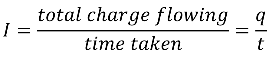
Now let small charge passes through a given area than the instantaneous current can be given as ![]()
Direction of electric current:-The direction of flow of positive charge or the direction in which electric field is applied gives the direction of electric current. This current is called conventional current. The direction of flow of electron gives direction of electronic current.
Unit of electric current:-
S.I unit of electric current is Ampere (A)
I.e. ![]()
Current through a conductor is said to be 1 ampere if one coulomb charge flows through any cross sectional area of the conductor in one second.
Electric current is a scalar quantity:-
Electric current has both magnitude as well as direction but it is not a vector quantity. Because it does not follow vector algebra but follow simple (scalar) algebra. The arrow represents the direction of current not that current is a vector quantity.
Types of current:-
Steady direct current (D.C):-
An electric current is said to be steady direct current if its magnitude and direction do not change with time
Alternating Current (A.C):-
An electric current is said to be alternating if its magnitude changes with time and polarity reveres periodically (repeats after a time interval)
2 DRIFT velocity m.imp
Drift velocity is defined as the average velocity with which free electrons in a conductor get drifted in a direction opposite to the direction of applied electric field.
(a)Expression for Drift Velocity:-
Let ![]() are the velocities of electrons in a conductor. Then average velocity is
are the velocities of electrons in a conductor. Then average velocity is
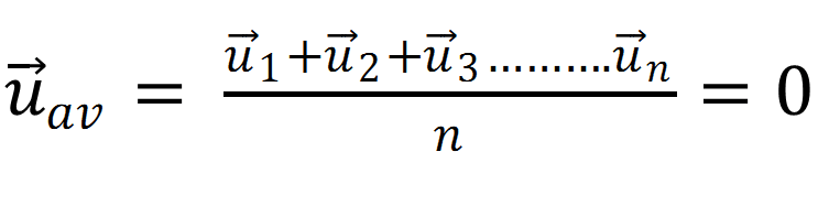 (1)
(1)
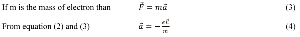
If ![]() is the applied electric field then force experienced by charge particles is
is the applied electric field then force experienced by charge particles is
![]() (2)
(2)
Note: – negative sign shows that E and F are opposite to each other.
The small interval of times between two successive collisions between electrons and ions in the conductor is called relaxation time (τ)
Hence after time τ the Final velocity can be given as (![]()
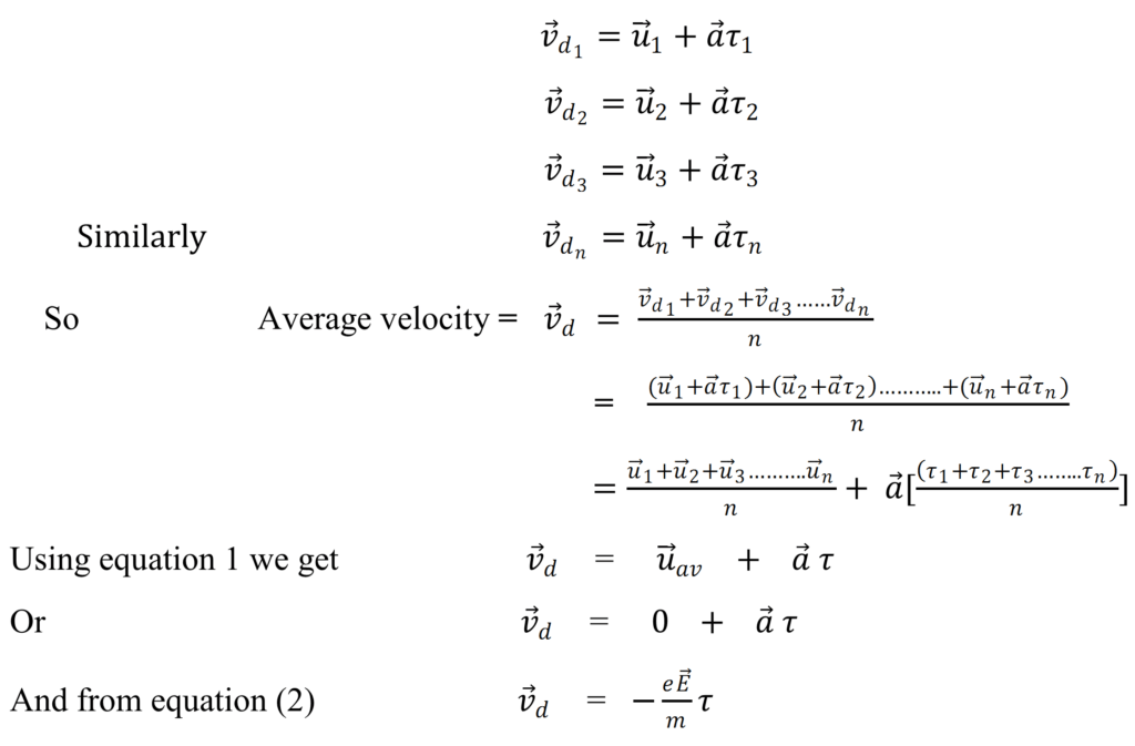
This is the required expression for drift velocity. Here negative sign show that and are in opposite direction.
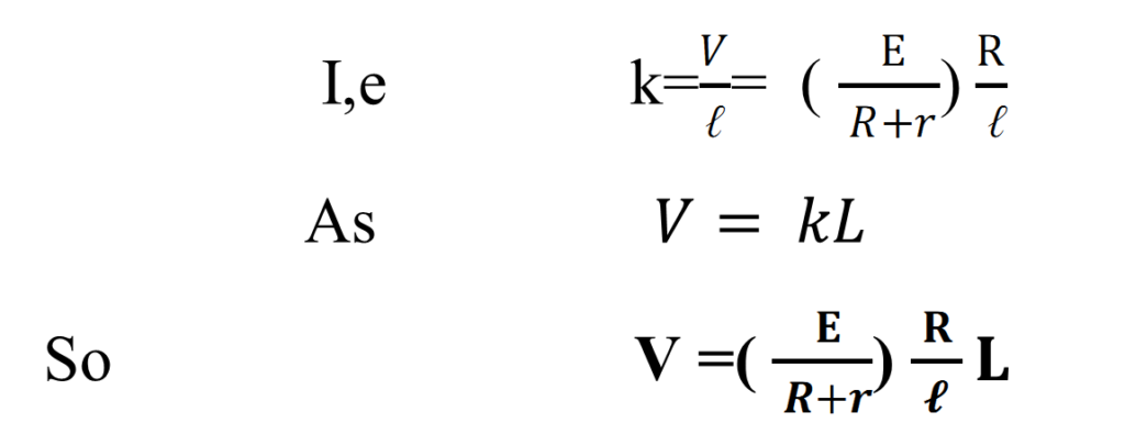
(b) Relation between Drift Velocity and Electric Current
Let us consider a conductor of length ℓ and area A. If V is the applied potential difference across the end of conductor of conductor, then electric field set up can be given as ![]()
As total volume of conductor![]()
If n is number of electron per unit volume than total electron=nal
If q is charge on 1 electron than charge on electrons ![]() (1)
(1)
So current flowing in the conductor
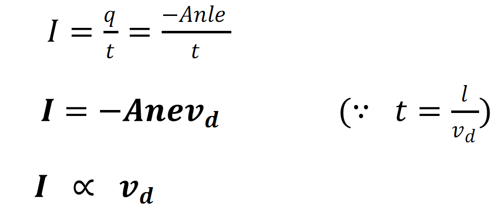
Hence greater is the drift velocity, greater is the current flow.
Q.1 The number density of free electrons in a copper conductor is 8.5 × 1028 m−3. How long does an electron take to drift from one end of a wire 3.0 m long to its other end? The area of cross-section of the wire is 2.0 × 10⁻⁶ m2 and it is carrying a current of 3.0 A.
Answer Number density of free electrons, n = 8.5 × 1028 m−3 Length of the wire, l = 3.0 m Area of the wire, A = 2.0 × 10⁻⁶ m2 Current carried by the wire, I = 3.0 A, which is given by the relation, =
 ⟹ 2.7 × 10⁴s
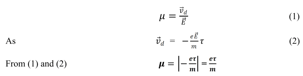
(3) Mobility (μ)
It is the ratio of drift velocity of current carriers and the applied electric field (E).
(4) Current density:-
Current density of a conductor is defined as the amount of current flowing per unit area of conductor perpendicular to the flow of current density (J ) is a vector quantity.
The current![]() through an element of surface area
through an element of surface area ![]() of a conductor is given by
of a conductor is given by
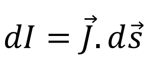
![]()
Unit: – the unit of electric current density is Am-2
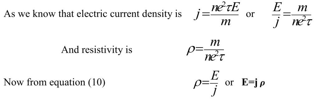
(a) Relation between Current Density and Drift Velocity:-
As we know that electric current and drift velocity is related as
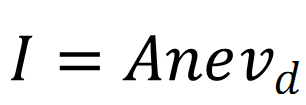
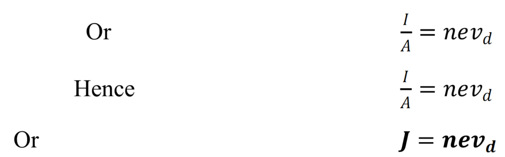
Hence larger the drift velocity larger will be the current density.
Q.2 A steady current flows in a metallic conductor of non-uniform cross- section. Which of these quantities is constant along the conductor: current, current density, electric field, drift speed?
When a steady current flows in a metallic conductor of non-uniform cross-section, the current flowing through the conductor is constant. Current density, electric field, and drift speed are inversely proportional to the area of cross-section. Therefore, they are not constant.
(5) OHM’s – LAW:- m.imp
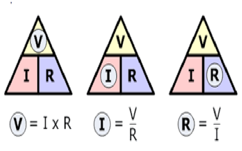
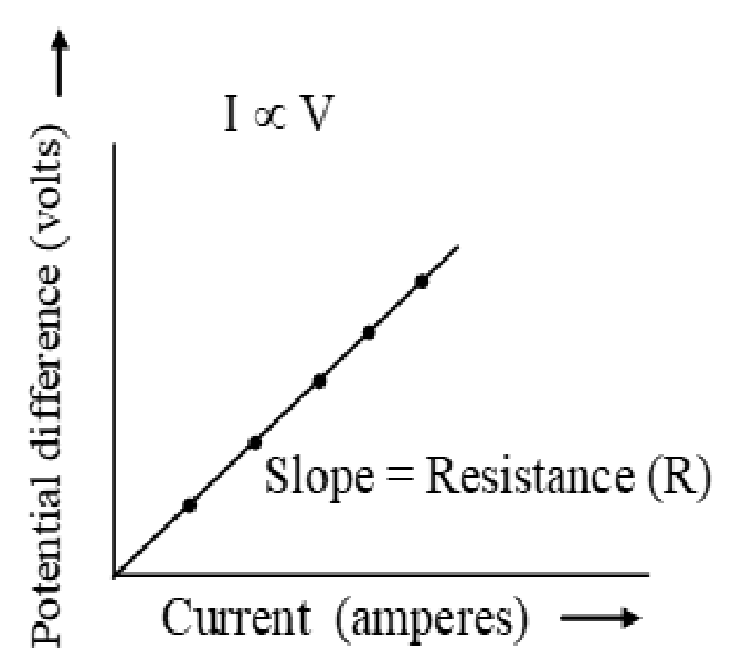
Ohm’s law states that the potential drop across the ends of a conductor of uniform cross section is directly proportional to the current (I) flowing through it provided constant physical condition such as temperature pressure etc. Mathematically, V ∝ I
Or V = IR
Or R =V/ I
Where R is constant of proportionality and called electric resistance of the conductor.
- The resistance R not only depends on the material of the conductor But also depends on the dimensions of the conductor.
(a) Ohmic and non – Ohmic conductors:-
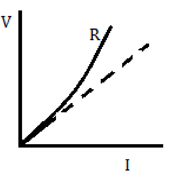
The conductor which obey ohm’s law called Ohmic conductor (i.e. V-I graph is a straight line) and which do not obey ohm’s law called non – Ohmic conductors (i.e. V-I graph is not straight line).
(b)Limitation/Failure/Exception of Ohm’s Law:-
According to ohm’s law the V-I graph should be straight line but there is some limitation of ohm’s law. These are as follow
(1) Potential Difference may Vary non – linearly with current:-
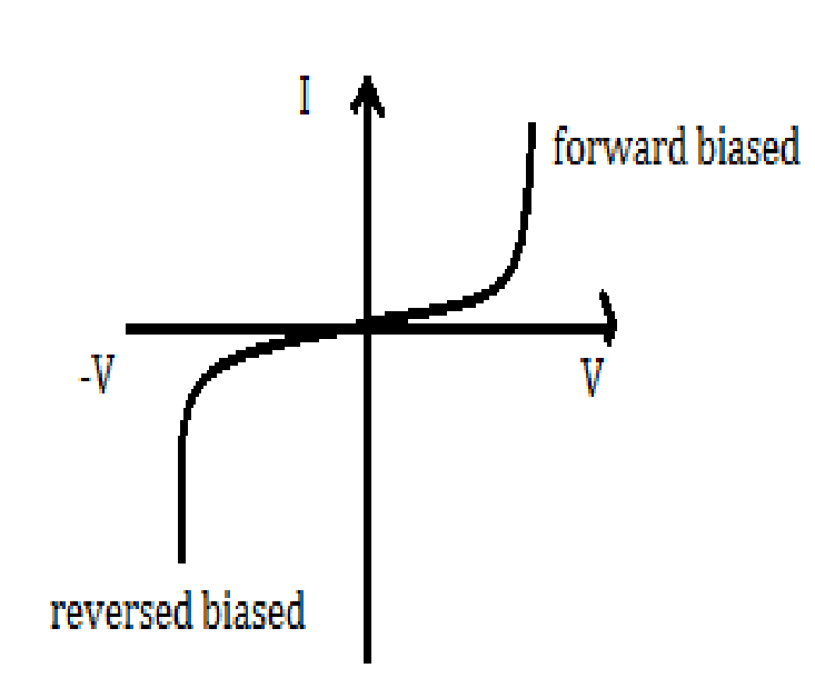
When current through a conductor increases, the conductor become hot (Temperature increases) due to which the V-I graph does not remain straight line hence ohm’s law fails.
Note:-Always current along y axis and V along x axis but here the result depends upon current so current along x axis and voltage along y axis is taken.
(2)Variation of potential difference may depend upon sign of the potential difference (related to semiconductor physics):-
For P-N junction diode when P-N junction diode is forward biased diode the current flows first slowly than rapidly. Similarly for reverse bias diode.

(3)The Current may be decreasing or increasing the potential difference:-
A thyristor shows this type of behavior .Here the curve AB represents the increase in current with decrease in potential.
(4) In GaAs there is more than one value of V for the same current I
I.e The relation between V and I is not unique.
(6) Resistance:- m.imp
The obstacle or the opposition in the flow of current in a conductor is called resistance of the conductor. Mathematically, It is defined as the ratio of applied potential difference to the current flowing through the conductor. i,e,
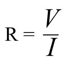
Unit of Resistance: –
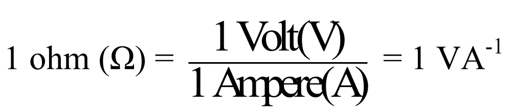
The resistance of a conductor is said to be 1 ohm if one ampere current flows through it when a potential difference of 1 volt is applied across it.
Cause of Resistance:-
When we apply potential difference, the electron starts flowing toward positive end and ions starts vibrating, As flow of electron is affected by ions or we can say the flow of electron is resist by vibrating ions .due to which resistance produces.
Symbol of Resistance:-
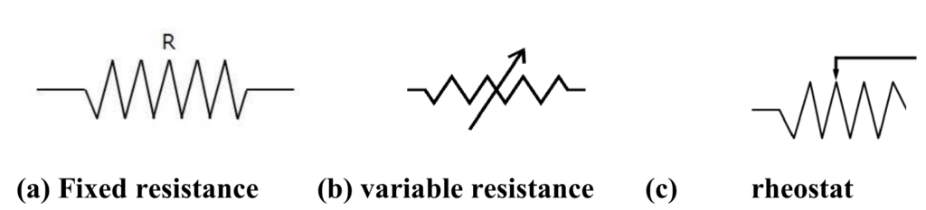
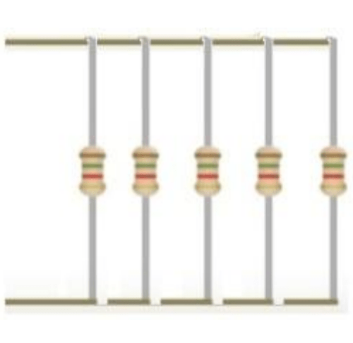
(7) Resistor and Their Color Code:-
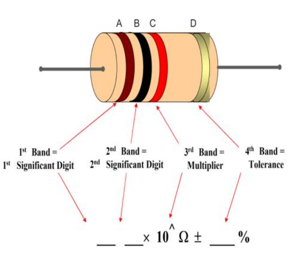
Resistor is a component of an electrical circuit which offers certain resistance to flow of current. They may be a wire, carbon resistance,
Color Code of Resistance:-
There are some color on carbon resistance given by manufacturer with the help of them we can calculate the resistance of capacitors. The sequence of below color can be remember as
(a)BB Roy Great Britain Has Very Good Wife.
(b)Black Brown Rods of Your Gate Becomes very Good When given Silver Color.
Formula for calculating resistance:-

|
|
COLOR |
FIGURE |
COLOUR(D) |
LOLERANCE |
|
B |
Black |
0 |
Gold |
± 5% |
|
B |
Brown |
1 |
Silver |
± 10% |
|
R |
Red |
2 |
No-Color |
± 20% |
|
O |
Orange |
3 |
||
|
Y |
Yellow |
4 |
tolerance |
|
|
G |
Green |
5 |
means |
|
|
B |
Blue |
6 |
Variation in the |
|
|
V |
Violet |
7 |
Value of restance. |
|
|
G |
Grey |
8 |
||
|
W |
white |
9 |
(8) Resistivity:- m.imp
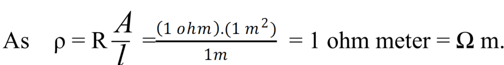
The resistance of a conductor depends upon l and area as Resistance is proportional to length
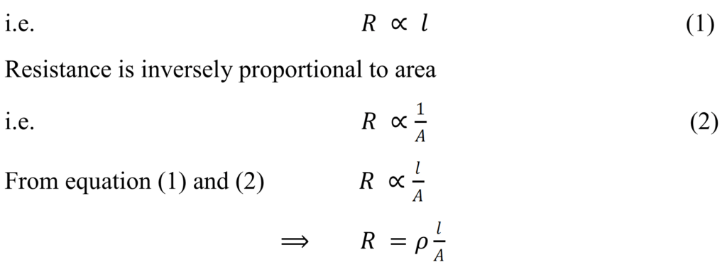
Here 𝜌 is constant of proportionality called resistivity or specific resistances. Its value depends upon nature of material and temperature.
Definition of Resistivity: – As ![]()

Hence resistivity is defined as the resistance of unit cube of substance.
Unit of resistivity: –
(a)Factor Affecting electrical Resistivity:-
Conclusion From Above Expression:-
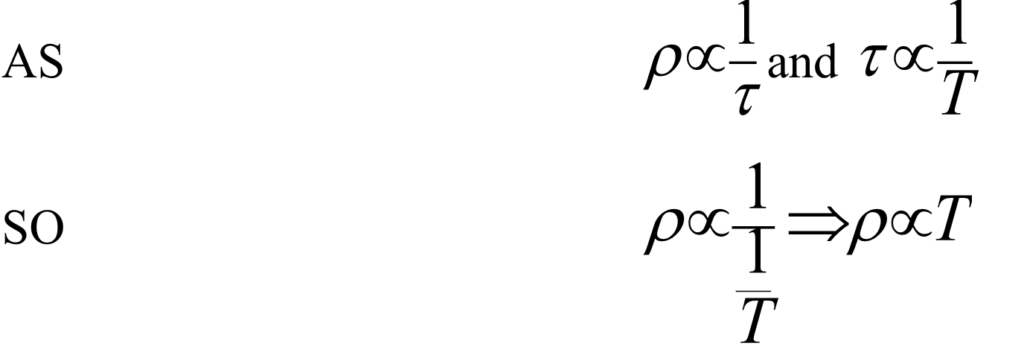
- 1 Resistivity is inversely proportional to number of electron. n ,So resistivity depend upon nature of material.
- It is inversely proportional to the average relaxation time
- It should be remembered that m, e are masses charge on electron so they are constant.
- Resistivity for perfect conductorsis 0.In perfect conductors there is no resistance at all.
- Resistivity for perfect insulatorsis infinite. There are so many obstacles as a result resistance is more so current cannot flow at all.
Q.3 A negligibly small current is passed through a wire of length 15 m and uniform cross section 6.0 × 10⁻⁷ m2 , and its resistance is measured to be 5.0 Ω. What is the resistivity of the material at the temperature of the experiment?
Answer Length of the wire, l =15 m Area a = 6.0 × 10⁻⁷ m2 Resistance R = 5.0 Ω Resistivity =ρ
Resistance is related with the resistivity as ![]()
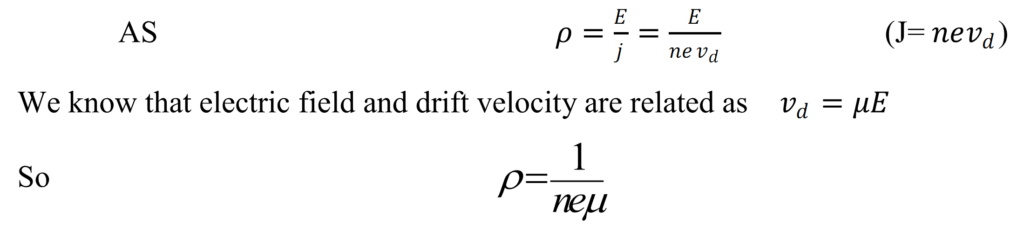
(b)Resistivity in term of current density:- microscopic form of ohms law
(c)Resistivity in term of electron mobility:-
(9) Temperature dependence of Resistivity:-
(1)Temperature dependence of Resistivity of metallic conductor:-
With increase of Temperature the Resistivity of a conductor increases.
Reason:-As with increase of Temperature the collision increases between electron and positive ions, Due to which average relaxation time decreases.
How resistance varies with temperature?(For metals)
With increase in temperature the random motion of molecules increases.
Initially the metal atoms are at rest but when the temperature is increased the metal atom starts vibrating as a result collision between metal atom and free electrons increases and as a result resistance increases.
Experimentally it was found:-
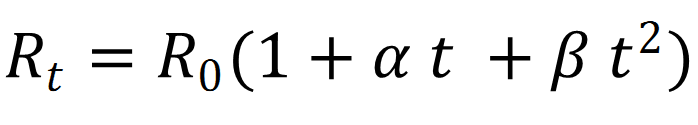
Where Rt=resistance at any temperature t. R0 =resistance at temperature 0.
As temperature was very less therefore β t2 is neglected.
Therefore ![]()
where α is known as temperature coefficient of resistance.
![]()
Conclusion:-
- α is positive for conductors.
- α is negative for insulators/semiconductors.
2 Temperature dependence of Resistivity of an alloy:-
Resistivity of alloys very less depends upon temperature. Due to which alloy of copper, nickel, iron and manganese called manganin is used for making resistance coil because its resistance is very high.
- Nichrome (which is an alloy of nickel, iron and chromium)
3 Temperature Dependence of Resistivity of semiconductor and insulator:-
With increase of temperature, the resistivity of semiconductor decreases.
Reason:-There is energy gap in semiconductor and insulator between valance band and conduction band .So with increase in temperature the electron cross the energy gap starts conducting hence resistivity decrease. Current flows due to conduction band. The energy gap is called Fermi energy gap.
- Alloys of metals usually have greater resistivity than that of their constituent metals.
- Alloys usually have lower temperature coefficients of resistance than pure metals.
- The resistivity of the alloy, manganin, is nearly independent of increase of temperature.
- The resistivity of a typical insulator is greater than that of a metal by a factor of the order of 1022.
Question4: A metal wire of diameter 2 mm and of length 100 m has a resistance of 0.5475 ohm at 20°C and 0.805 ohm at 150°C. Find the value of its resistance at 0°C
Solution: If R20 and R150 be the resistances at temperatures 20°C and 150°C respectively and a be the temperature coefficient of resistance

Q.5 At room temperature (27.0 °C) the resistance of a heating element is 100 Ω. What is the temperature of the element if the resistance is found to be 117 Ω, given that the temperature coefficient of the material of the resistor is α =1.70×10⁻⁴ 0C-1
Answer Room temperature, T = 27°C Resistance of the heating element at T, R = 100 Ω Let T1 is the increased temperature of the filament. Resistance of the heating element α=1.70×10⁻⁴ 0C-1
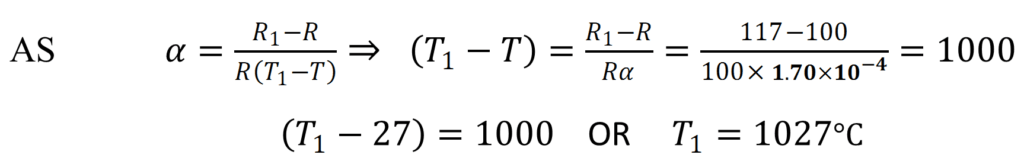
Therefore, at 1027°C, the resistance of the element is 117Ω.
(10) Conductance and conductivity:-
Conductance:- (G) Conductance means something which conducts the current. Greater the resistance lesser the conductance and vice-versa![]()
Unit :- (s) Siemen = ohm-1(Ω-1) =mho
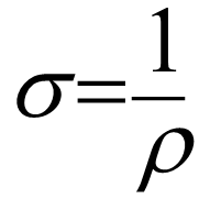
Conductivity: – (σ) The reciprocal of resistivity is called Conductivity.
Unit:- ohm metre-1(Ω-1) or mho metre-1 siemen metre-1 (sm-1)
(11)Combination of Resistance:- m.imp
(a)Resistance in series
Resistance are said to be connected in series when potential difference applied across combination cause production of current. Let us consider three resistors are connected series. Let I is current passing through each resistor then total potential difference applied can be given as
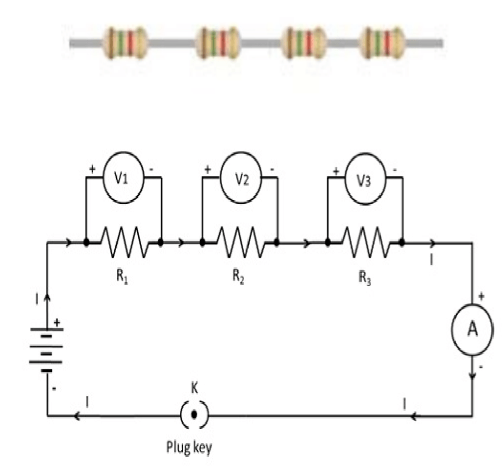
V=V1+V2+V3 (1)
Where

(2)
From equation (1) and (2) ![]()
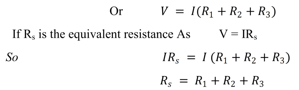
Equivalent Resistance:-
When the three resistors are connected in series, equivalent resistance of the series combination is equal to sum of individual resistance. Equivalent resistance is always greater than largest resistance.
Conclusion:-
- Current through all the resistance (resistor) is same.
- The potential difference across any resistor is proportional to its resistance.
- Current is independent of position of resistor.
(b)Resistors in Parallel:-
Resistor are said to be connected in parallel, if potential difference across each of them is equal to the applied potential difference. Let us consider three resistors are connected in parallel i.e.
Let I is total current passing through resistor. Than
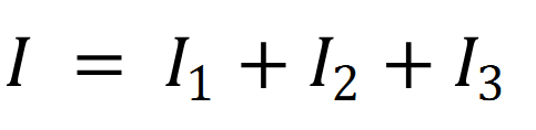
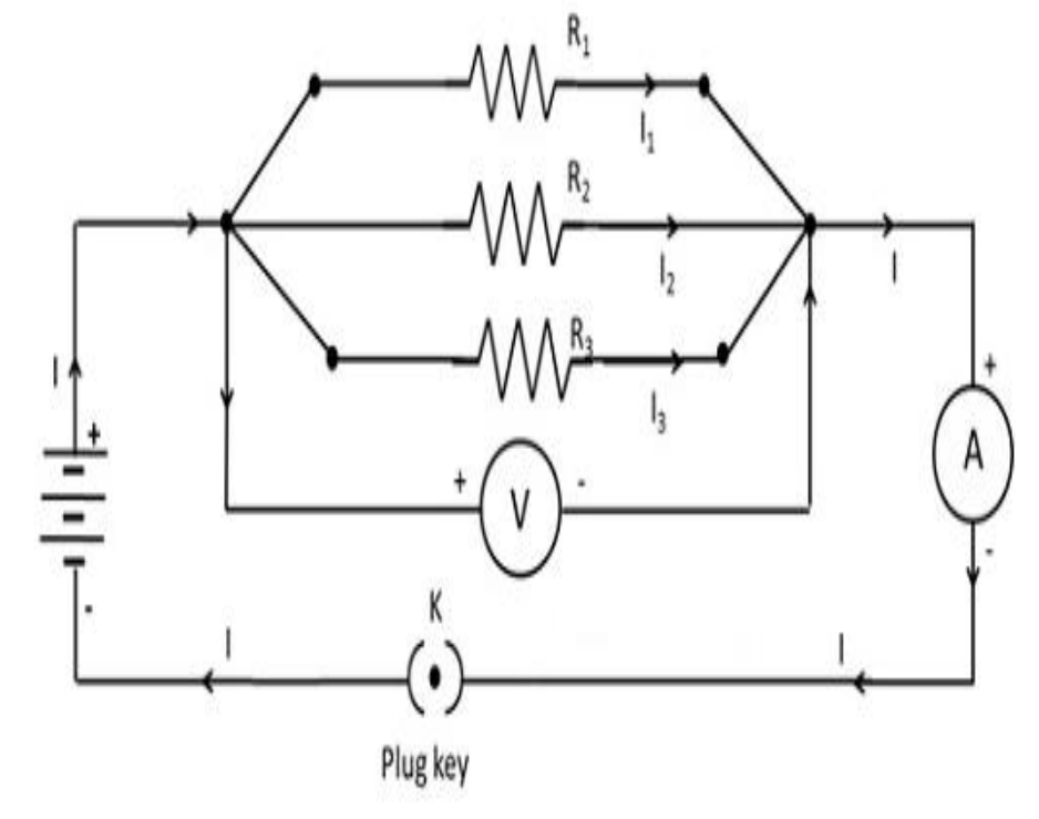
Equivalent Resistance:-
Equivalent Resistance of parallel combination is equal to the sum of reciprocal of individual resistance.
Conclusion:-
- Potential difference across the entire resistor is the same.
- The current through any resistor is inversely proportional to its resistance.
Q.6 given n resistors each of resistance R, how will you combine them to get the (i) maximum (ii) minimum effective resistance? What is the ratio of the maximum to minimum resistance?
Total number of resistors = n Resistance of each resistor = R
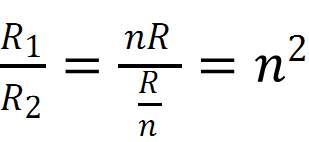
- When n resistors are connected in series, effective resistance R1is the maximum, given by the product nR.
- When n resistors are connected in parallel, the effective resistance (R2) is the minimum, given by the ratio
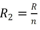
- The ratio of the maximum to the minimum resistance is
Q.7 (a) three resistors 1 Ω, 2 Ω, and 3 Ω are combined in series. What is the total resistance of the combination?
(b) If the combination is connected to a battery of emf 12 V and negligible internal resistance, obtain the potential drop across each resistor.
Answer (a) three resistors of resistances 1 Ω, 2 Ω, and 3 Ω are combined in series. Total resistance of the combination is given by the algebraic sum of individual resistances.
Total resistance = 1 + 2 + 3 = 6 Ω
(b) Current flowing through the circuit = I Emf of the battery, E = 12 V Total resistance of the circuit, R = 6 Ω The relation for current using Ohm’s law is, ![]()
Potential drop across 1 Ω resistor = V1 as V1 = 2 × 1= 2 V … (i)
Potential drop across 2 Ω resistor = V2 as V2 = 2 × 2= 4 V … (ii)
Potential drop across 3 Ω resistor = V3 as V3 = 2 × 3= 6 V … (iii)
Therefore, the potential drop across 1 Ω, 2 Ω, and 3 Ω resistors are 2 V, 4 V, and 6 V respectively.
Q.8 (a) three resistors 2 Ω, 4 Ω and 5 Ω are combined in parallel. What is the total resistance of the combination?
(b) If the combination is connected to a battery of emf 20 V and negligible internal resistance, determine the current through each resistor, and the total current drawn from the battery.
Answer (a) There are three resistors of resistances, R1 = 2 Ω, R2 = 4 Ω, and R3 = 5 Ω they are connected in parallel. Hence, total resistance (R) of the combination is given by
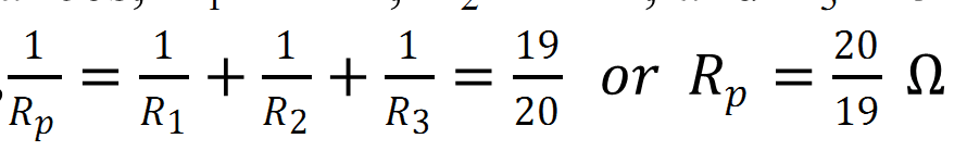
Therefore, total resistance of the combination is ![]()
(b) Emf of the battery, V = 20 V Current (I1) flowing through resistor R1 is given by ![]()
Current (I2) flowing through resistor R2 is given by ![]()
Current (I3) flowing through resistor R3 is given by ![]()
Total current, I = I1 + I2 + I3 = 10 + 5 + 4 = 19 A
Q.9 Given the resistances of 1 Ω, 2 Ω, 3 Ω, how will be combine them to get an equivalent resistance of (i) (11/3) Ω (ii) (11/5) Ω, (iii) 6 Ω, (iv) (6/11) Ω?

Q.10 Determine the equivalent resistance of networks shown in Fig
All the four resistors are connected in series. Hence, equivalent resistance of the given circuit is
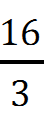 Ω.
Ω.(b) It can be observed from the given circuit that five resistors of resistance R eac
h are connected in series. Hence, equivalent resistance of the circuit = R + R + R + R + R = 5 R
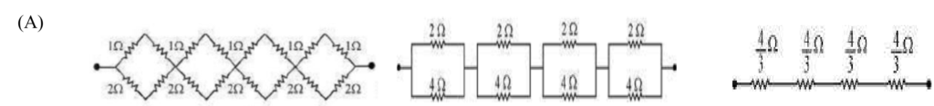
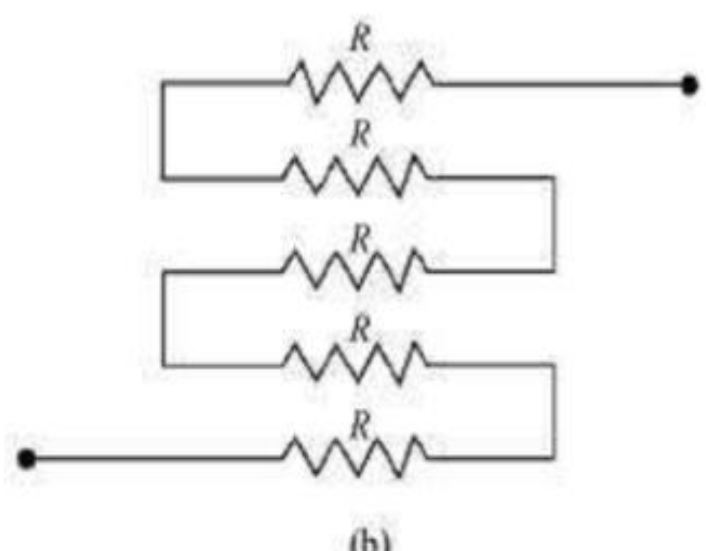
Q.11 Determine the current drawn from a 12 V supply with internal resistance 0.5 Ω by the infinite network shown in Fig. Each resistor has 1 Ω resistance.
Answer the resistance of each resistor connected in the given circuit, R = 1 Ω
Equivalent resistance of the given circuit = R’
The network is infinite. Hence, equivalent resistance is given by the relation,

Negative value of R’ cannot be accepted. Hence, equivalent resistance, ![]()
Internal resistance of the circuit, r = 0.5 Ω
Hence, total resistance of the given circuit = 2.73 + 0.5 = 3.23 Ω
Supply voltage, V = 12 V
According to Ohm’s Law, current drawn from the source is given by the ratio, = 3.72 A
(12) Thermistor:-
Thermistor is made up of semi-conductor material which is highly heat sensitive. Its resistance change with change in temperature.
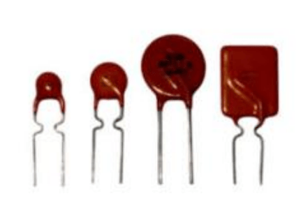
Properties of Thermistor:-
- (1)The resistance of Thermistor change with temperature.
- (2)The resistance may decrease or increase with temperature.
Uses:-
(1)They are used for measuring temperature.
(2)They are used for making motors, transformers and generators.
(3)They are used for controlling temperature.
(13) Super Conductor and Super conductivity:-
The conductors which have zero resistance to electricity is called super conductor. The phenomenon by which a conductor becomes super conductor at a particular temperature (Critical temperature) is called super conductivity.
Critical temperature:-
The temperature at which a substance becomes super conductor is called critical temperature
Range:-
At 2-5 ok almost all elements act as superconductor.
Critical temperature TC (K) of some superconducting materials
|
Hg |
4.2 |
|
Au2Bi |
1.7 |
|
YBa2Cu3O7 |
90 |
|
Tl2Ba2Ca2Cu3O10 |
120 |
Application of superconductor
- Superconductor is used in making large electromagnets. This is because no heat is generated when a current flows through a superconductor.
- Superconductor may be used for transmission of electric power without power losses.
- Super conductors can be used for making high speed computers.
(14) A Cell And Related TERMS: – m.imp
(a)A Cell:-
A cell is a device which provided the necessary potential difference to an electric circuit to maintain a continuous flow of current through it.
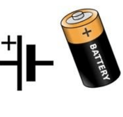
Symbol of Cell: – Here longer lines show positive terminal and negative by smaller line.
(b)Electromotive Force (EMF)
Emf is the potential difference in a cell when the circuit is open means no current is drawn from cell. Or the work done by a cell to bring a unit +ve charge from one terminal to the other terminal of cell is called emf.
Unit of a cell: –
Si unit of cell is volt (v) or joule /coulomb.
(c)Terminal potential difference: –
The potential difference in a closed circuit is called terminal potential difference.
(d)Internal resistance of a call:-
The resistance offered by electrolyte of the cell is called internal resistance of cell. It is denoted by r.
(e)Relation between E.M.F and Terminal Potential Difference.
Or. Expression for internal resistance of a cell. m.imp
According to ohms law the current through the circuit is ![]() (1)
(1)
Or ![]()
Where r is the internal resistance of cell and E is the potential difference when circuit is open.
Potential difference can be written as V=IR
So by (1) ![]()
⇒ ![]() (2)
(2)
Which show that EMF is always greater than potential Difference of cell.
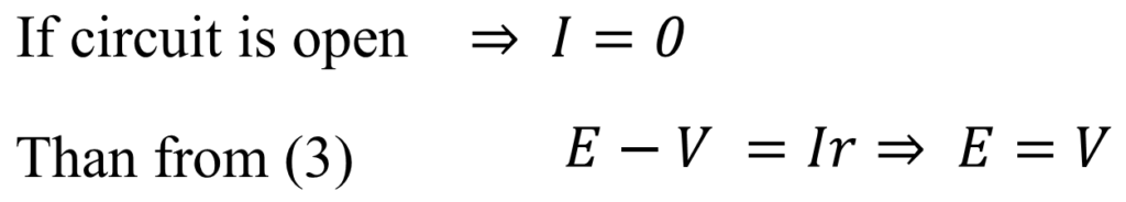
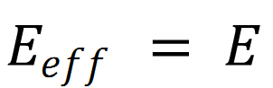
Hence if there is no internal resistance then emf is equal to potential difference.
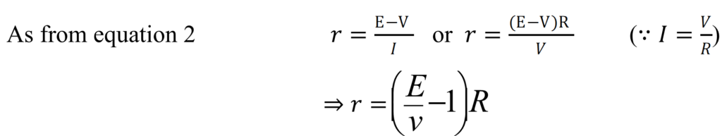
This is the required expression for internal resistance of a cell
Q.12 a high tension (HT) supply of, say, 6 kV must have a very large internal resistance. Why?
In order to prohibit the current from exceeding the safety limit, a high tension supply must have a very large internal resistance. If the internal resistance is not large, then the current drawn can exceed the safety limits in case of a short circuit.
Q.13 The storage battery of a car has an emf of 12 V. If the internal resistance of the battery is 0.4Ω, what is the maximum current that can be drawn from the battery?
Answer Emf of the battery, E = 12 V Internal resistance of the battery, r = 0.4 Ω Maximum current drawn from the battery = I According to Ohm’s law,
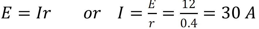
The maximum current drawn from the given battery is 30 A.
Q.14 A battery of emf 10 V and internal resistance 3 Ω is connected to a resistor. If the current in the circuit is 0.5 A, what is the resistance of the resistor? What is the terminal voltage of the battery when the circuit is closed?

- Difference between Emf and Potential difference:-
|
Sr no. |
Electro motive force(emf) |
Potential difference |
|
1. |
Emf is the Potential difference |
1 Potential difference is Created |
|
When cell is open. |
When cell is closed. |
|
|
2. |
It does not depend upon external Resistance. |
2 It depend upon external Resistance. |
|
3. |
Emf of a cell is greater than |
3 Potential difference is |
|
Potential difference |
Smaller than Emf of a cell |
15 GROUPING OF CELLS
There are three types of grouping of cells.
1 In series 2 in parallel 3 Mixed shells
- Cell in series:-
In series combination, the positive of a cell is connected to the positive terminal of the other cell.
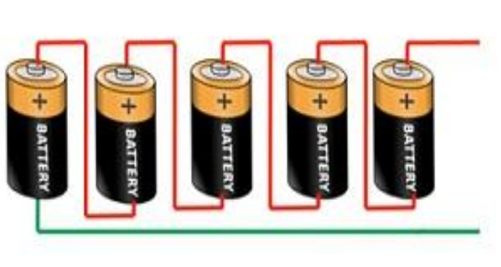
Let n cells having each emf E, internal resistance r connected in series to an external resistance R.
Then the total emf of cell is

As the cells are in series so internal resistance are in series

Here internal resistance and external resistance R is in series so total equivalent resistance
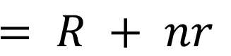
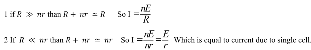
The current flowing in the circuit is 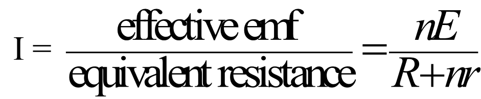
Special cases:-
- Cell in Parallel:-
Let us consider m identical cells each of emf E and internal resistance r connected in parallel to external resistance R. If cells are connected in parallel . Than
Resistance of cells is in parallel so

(iii)Mixed Grouping of Cells: – m.imp
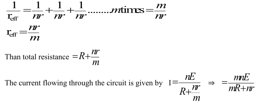
Let us consider a number of identical cells each of emf E and internal resistance r. let these cells be arranged in m rows and each rows contains n cells. This arrangement of cells is connected to an external resistance R.
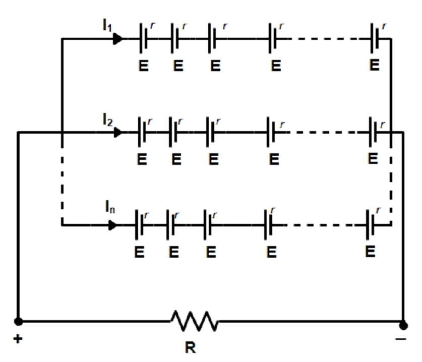
Total emf Of n cells in row is ![]()
Cells in parallel so ![]()
The internal resistance in each row in series so = nr there are m rows in parallel having each internal resistance, so
The current will be maximum if ![]()
are minimum. i.e.
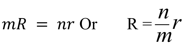
Thus to obtain maximum current in the circuit, the grouping of cells must be done in such a way that external resistance is equal to effective interval resistance of cells.
Q.15 A storage battery of emf 8.0 V and internal resistance 0.5 Ω is being charged by a 120 V dc supply using a series resistor of 15.5 Ω. What is the terminal voltage of the battery during charging? What is the purpose of having a series resistor in the charging circuit?
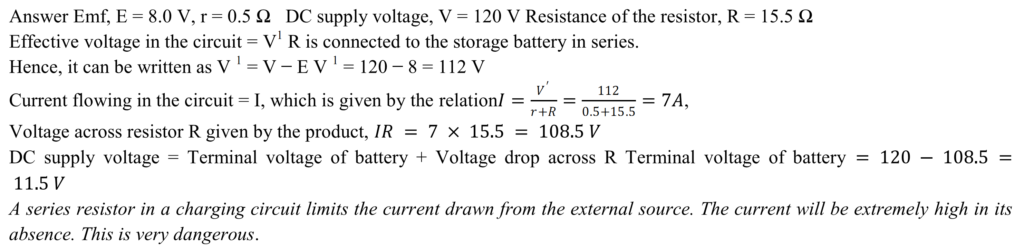
A series resistor in a charging circuit limits the current drawn from the external source. The current will be extremely high in its absence. This is very dangerous.
2 (b) electric measurements
Kirchhoff’s laws are used to find out the directions of current in any part of the circuit.
- Kirchhoff’s I st Law (Junction law or current law) m.imp
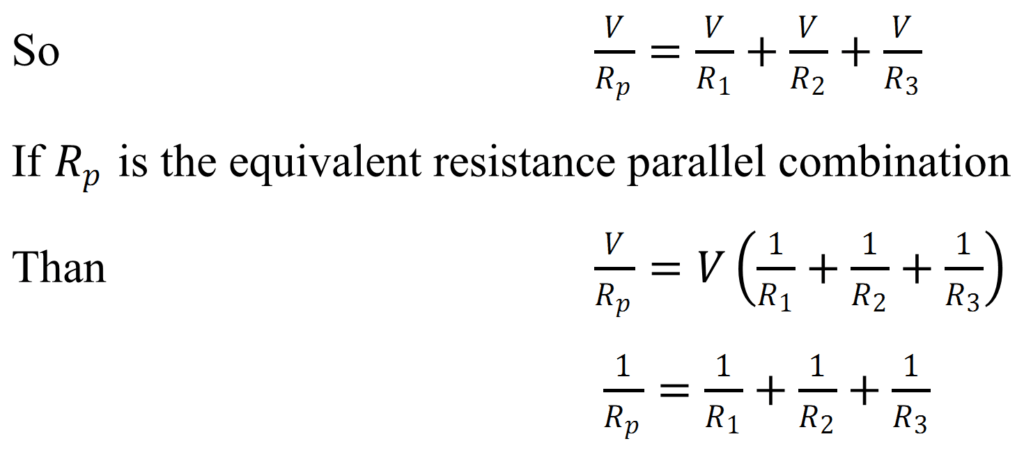
According to Kirchhoff’s I st Law in any electric circuit, the algebraic sum of all the current meeting at any junction is zero. Or The sum of current meeting at the junction is equal to the sum of current leaving the junction.
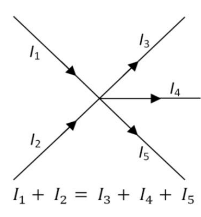
I, e- ∑ I=0
Sign Convention:-
The current flowing toward Junction is taken positive & current leaving the junction are taken negative . In fig. Current are taken ![]()
positive & ![]() are taken
are taken
As ![]()
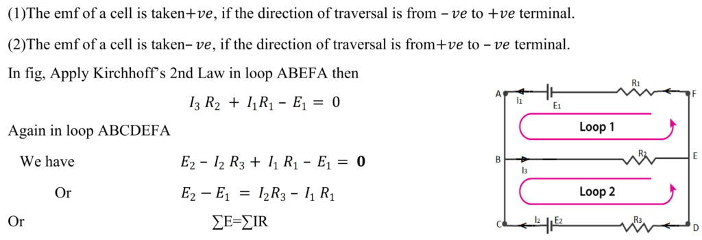
Kirchhoff’s 2 nd Law (loop law or Voltage Law) m.imp
According to Kirchhoff’s 2nd Law, the algebraic sum of the emf in any closed loop is equal to the sum of the product of the current & resistance in it.
I.e. ∑ E = ∑ IR
Sign Convention: –
- WHEAT STONE BRIDGE m.imp
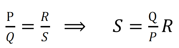
It is an arrangement of four resistances, in which one unknown resistance is determined quickly and accurately in term of three other known resistances.
Principle:-
Let S be the unknown resistance, the resistance R is adjusted in such a way that there is no deflection in galvanometer in such situation
Construction:-
A wheat stone bridge is consisting of four resistances P, Q, R, and S as four arms of a quadrilateral. A battery of emf E is connected between A& C & a galvanometer between B & D. As shown in fig.
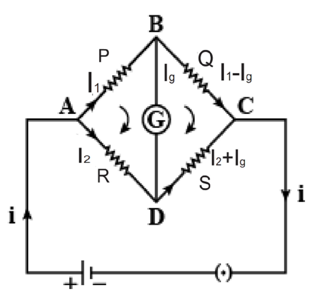
Proof:-

Hence when there is no deflection in galvanometer then bridge is balanced & unknown resistance can be calculated.
Sensitivity of a wheat stone bridge :-
A wheat stone bridge is said to be sensitive if it shows a large deflection in galvanometer for a small change of resistance in the wire. Greater is the sensitivity; larger is the accuracy in the measurement.
Merits/ advantage of Wheatstone Bride:-
(1) The resistance measured by Wheatstone bride does not depend upon internal resistance of battery.
(2)There is no need to measure voltage and current so it is more accurate method because ammeters and voltmeter are not ideal.
(3)The accuracy of resistance measurement can be increased by using high ratio of P and Q.
-
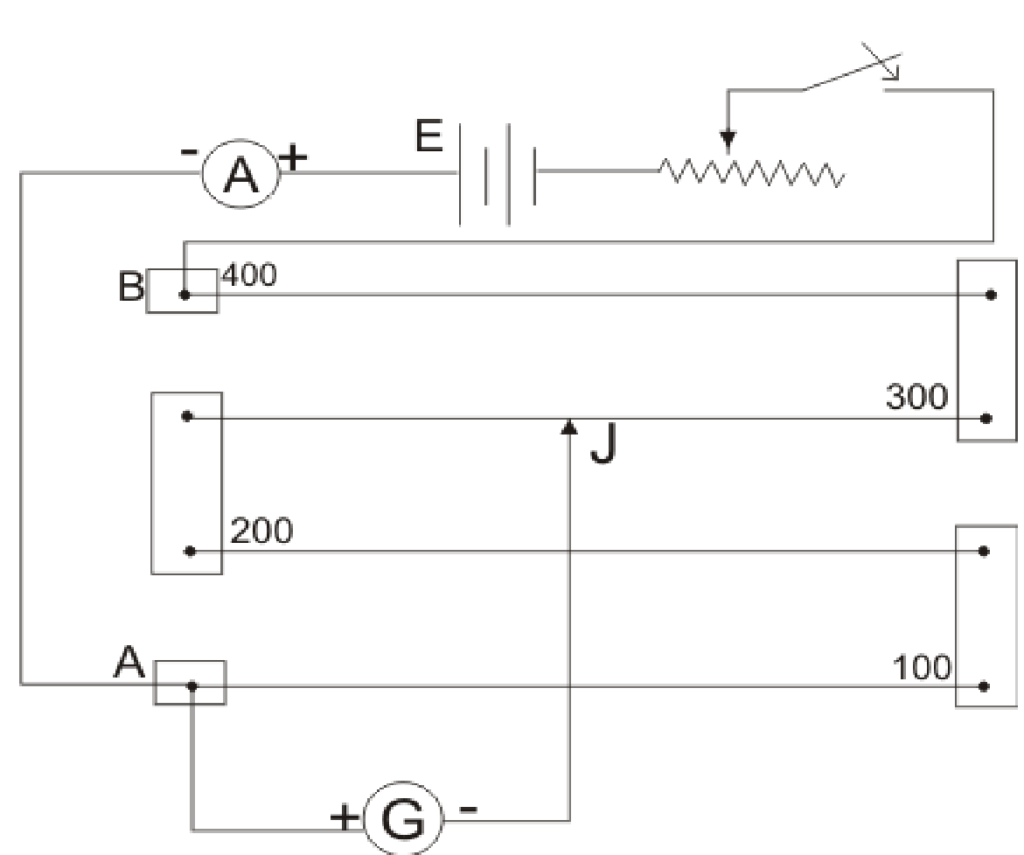
Metre Bridge or Slide wire bridge:- m.imp
It is the simplest measuring unit based on the practical application unit of wheat stone bridge which is used for measuring unknown resistance.
Principle:-
Its working is based on the principle of wheat stone bridge, i.e. when there is no deflection in galvanometer then bridge is balanced & unknown resistance can be calculated.
When the bridge is balanced then ![]()
Construction:- A metre bridge is consisting of a one metre magnanin or constantan wire fixed on a wooden board along with metre scale with the help of copper strips A& C. Two resistances R (Resistance box) & S are connected between these copper stripes with the help of another copper strips. A Galvanometer is connected with jockey.
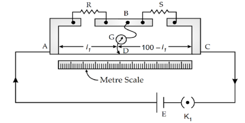
Working:- When jockey is moved at the wire, then at a certain point B the bridge becomes balanced in that situation,

(where r is the resistance per unit length of the wire)
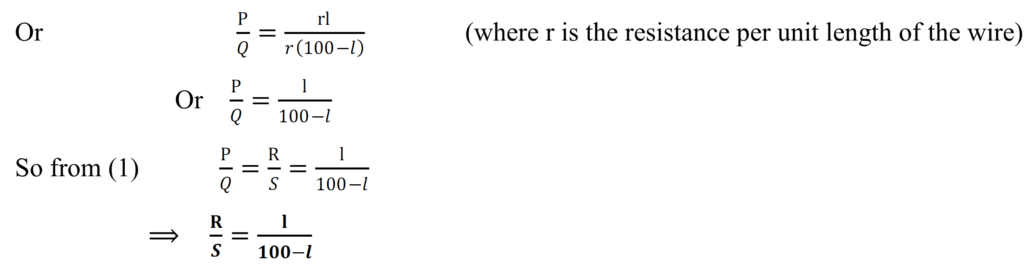
Hence if we know the value of R, l and 100-l than S can be calculated.
Q.16 (a) In a metre bridge the balance point is found to be at 39.5 cm from the end A, when the resistor Y is of 12.5 Ω. Determine the resistance of X. Why are the connections between resistors in a Wheatstone or meter bridge made of thick copper strips?
(b) Determine the balance point of the bridge above if X and Y are interchanged.
(c) What happens if the galvanometer and cell are interchanged at the balance point of the bridge? Would the galvanometer show any current?

Answer a metre bridge with resistors X and Y is represented in the given figure.
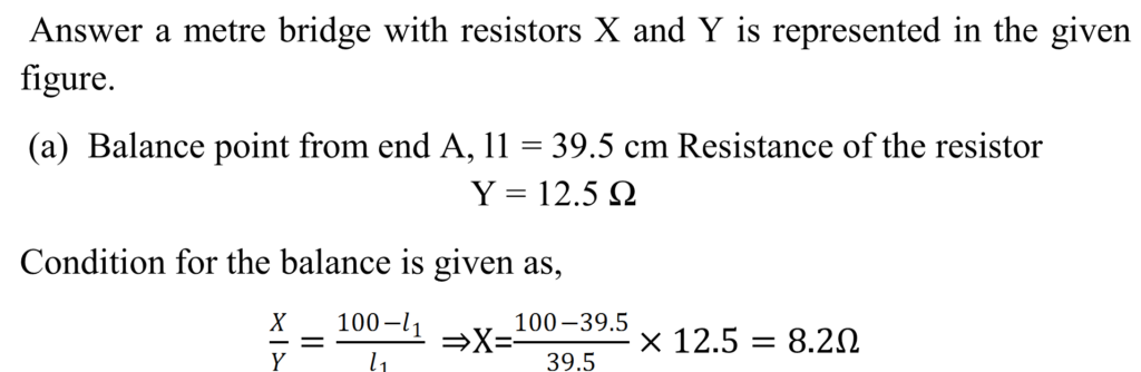
The connection between resistors in a Wheatstone or metre bridge is made of thick copper strips to minimize the resistance, which is not taken into consideration in the bridge formula.
(b) If X and Y are interchanged, then l1 and 100−l1 get interchanged. The balance point of the bridge will be 100−l1 from A 100−l1 = 100 − 39.5 = 60.5 cm Therefore, the balance point is 60.5 cm from A.
(c) When the galvanometer and cell are interchanged at the balance point of the bridge, the galvanometer will show no deflection. Hence, no current would flow through the galvanometer.
-
Potentiometer:- m.imp
A potentiometer is a device which is used to measure a unknown emf or potential difference accurately.
Construction:-
A potentiometer is consist of a long wire AB of length four metre fixed on a wooden board with the help of a copper strips along with metre scale. The ends A & B are connected to a strong battery, key and rheostat. Here rheostat provides a constant current, when Jockey is moved on the wire.
Principle:-
The potentiometer is based on the principle that when a constant current flow across the length of the wire of uniform area, then the potential drop is directly proportional to length of the wire.
Working:-
As shown in the fig:- If we connect a voltmeter between the end A & the Jockey, then we can see that when jockey move on the wire then potential difference varies in the voltmeter as
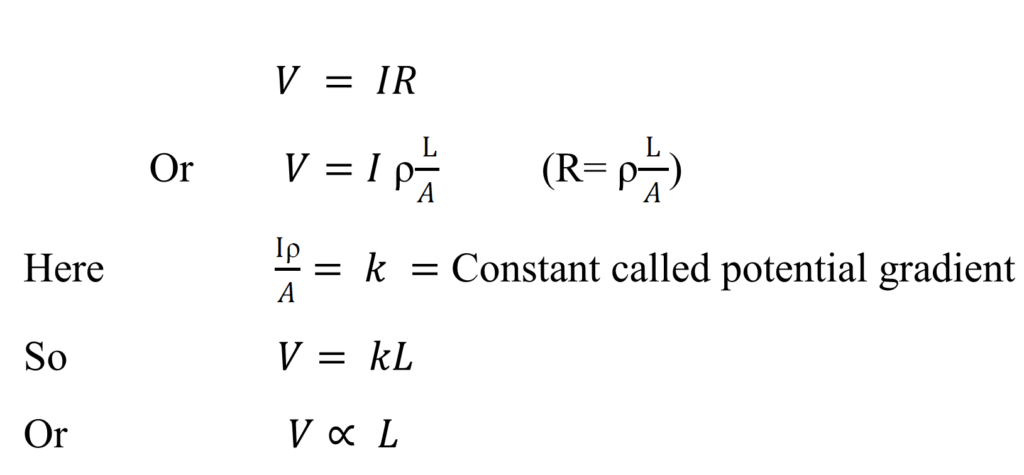
This is the principle of the potentiometer.
- The potentiometer has the advantage that it draws no current from the voltage source being measured.
- As such it is unaffected by the internal resistance of the source.
- In general alloys like constantan or manganin are used as potentiometer wire.
Constantan or manganin are used as potentiometer wire because of the following two reasons which are listed below:- - Constantan or manganin wire posses high specific resistance
- Constantan or manganin wire posses low temperature coefficient.
Q.17 how a potentiometer behave as an ideal voltmeter.
A ideal voltmeter does not change the potential difference of the circuit, it have infinite resistance. But it is not possible that a voltmeter have infinite resistance. But a potentiometer does not draw any current from the circuit, so it behaves as an ideal voltmeter.
- Application of a potentiometer:- m.imp
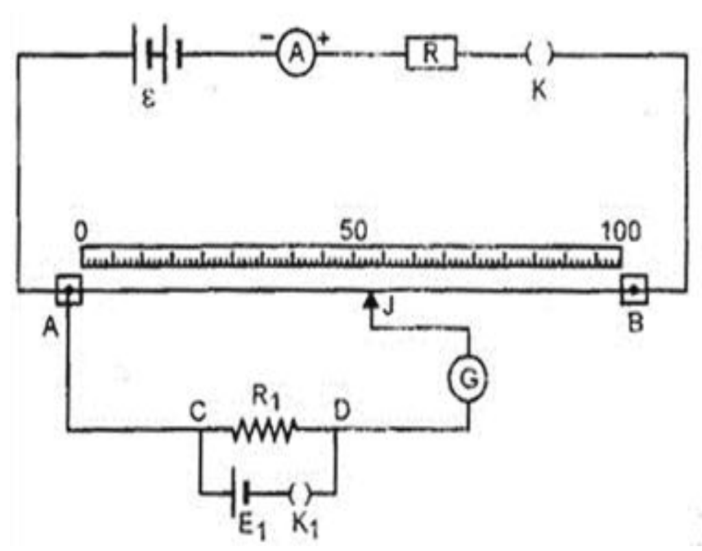
- Comparison of emf of two primary cells.
A circuit diagram for comparing of emf of two cells is as shown in fig. in this diagram, the ends of the wire PQ are connected with a battery, a key & rheostat for obtaining constant current supply galvanometer is connected with jockey & the other end of the Galvanometer may be connected to a cell either 1 or 2 through a two way key system. When the connection 1 & 3 are joined & the jockey is moved at the wire then supposes at L1 the deflection in the Galvanometer becomes zero. At that situation:
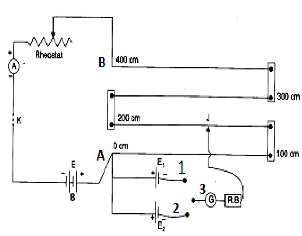
![]()
Now when the connection 1 & 3 are joined then we obtain

Hence we can compare emf of two cells by using potentiometer.
Q.18 in a potentiometer arrangement, a cell of emf 1.25 V gives a balance point at 35.0 cm length of the wire. If the cell is replaced by another cell and the balance point shifts to 63.0 cm, what is the emf of the second cell?
Answer Emf E1 = 1.25 V Balance point of the potentiometer, l1= 35 cm the cell is replaced by another cell of emf E2. New balance point of the potentiometer, l2 = 63 cm.
The balance condition of the potentiometer is given as ![]()
(b)To determine the internal resistance of a cell:-
As shown in fig. firstly connects the key K so that the constant current flows in the circuit with the help of a rheostat. In this situation when jockey is moved on the wire then suppose at AJ = L1 the galvanometer shows no deflection. Now the emf of the cell E= potential difference across the length of the wire
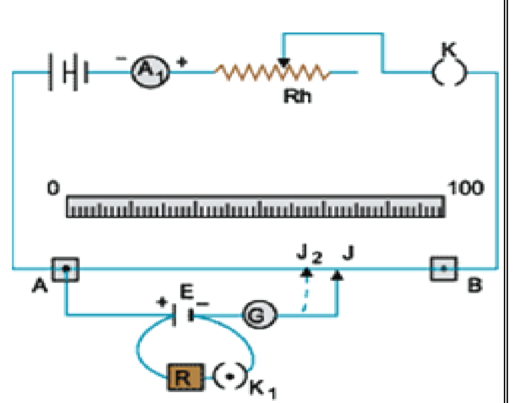
Or ![]()
Now when key K1 is closed, then galvanometer shows no deflection at ![]() .
.
Then Potential difference between two poles of the cell V= potential difference across the length of the wire
Hence we can calculate internal resistance of the cell.
- Determination of Potential difference using potentiometer:-
A battery of emf E is connected with resistance box R & a key between terminals A & B. A resistance R1 is connected to cell E1 and key K1 in series.
Theory and working:-
After closing the key K1 the current flows through resistance R1 & when jockey is moved on the wire then suppose at ![]()
the Galvanometer shows no deflection.
Then the maximum amount of the current flowing in the circuit is
![]()
So the potential drop across the length of the wire will be
Where R is the resistance of the wire of length L .
Now potential gradient = fall of potential per unit length
SENSITIVENESS OF POTENTIOMETER
A potentiometer is sensitive if
(1)It is measure a very small potential difference and
(2) If there is large change in length for small change in potential difference.
The sensitivity of a potentiometer may be increased by increasing the length of the wire.
21 Difference between potentiometer & voltmeter
|
Potentiometer |
Voltmeter |
|
1 It measures emf of the cell accurately |
1 Its measured emf is aproximately.
|
|
2 Its sensitivity is high |
2 Its sensitivity is low |
|
3It is based on null deflection method |
3It is based on deflection method.
|
|
4It can be used for various purposes. |
4It can be used only to measure emf & potential difference |
Q.19 Figure shows a potentiometer with a cell of 2.0 V and internal resistance 0.40 Ω maintaining a potential drop across the resistor wire AB.
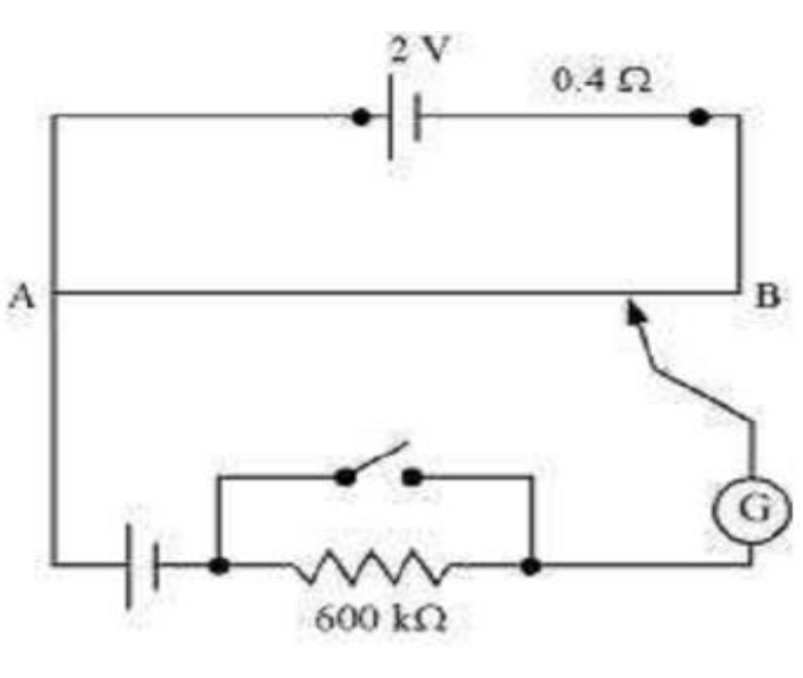
A standard cell which maintains a constant emf of 1.02 V gives a balance point at 67.3 cm length of the wire. To ensure very low currents drawn from the standard cell, a very high resistance of 600 kΩ is put in series with it, which is shorted close to the balance point. The standard cell is then replaced by a cell of unknown emf ε and the balance point found similarly, turns out to be at 82.3 cm length of the wire.
(a) What is the value ε ? (b) What purpose does the high resistance of 600 kΩ have? (c) Is the balance point affected by this high resistance? (d) Is the balance point affected by the internal resistance of the driver cell? (e) Would the method work in the above situation if the driver cell of the potentiometer had an emf of 1.0 V instead of 2.0 V?
(f ) Would the circuit work well for determining an extremely small emf, say of the order of a few mV (such as the typical emf of a thermo-couple)? If not, how will you modify the circuit?
Answer (a) emf of the cell, E1 = 1.02 V Balance point, l1 = 67.3 cm A cell of unknown emf, ε, replaced the standard cell. Therefore, new balance point on the wire, l = 82.3 cm
The relation connecting emf and balance point is
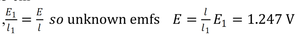
,
(b) The purpose of using the high resistance of 600 kΩ is to reduce the current through the galvanometer when the movable contact is far from the balance point.
(c) The balance point is not affected by the presence of high resistance.
(d) The point is not affected by the internal resistance of the driver cell.
(e) The method would not work if the driver cell of the potentiometer had an emf of 1.0 V instead of 2.0 V. This is because if the emf of the driver cell of the potentiometer is less than the emf of the other cell, then there would be no balance point on the wire. (f) The circuit would not work well for determining an extremely small emf. As the circuit would be unstable, the balance point would be close to end A. Hence, there would be a large percentage of error. The given circuit can be modified if a series resistance is connected with the wire AB. The potential drop across AB is slightly greater than the emf measured. The percentage error would be small.
Q.20 Figure shows a potentiometer circuit for comparison of two resistances. The balance point with a standard resistor R = 10.0 Ω is found to be 58.3 cm, while that with the unknown resistance X is 68.5 cm. Determine the value of X. What might you do if you failed to find a balance point with the given cell of emf ε?
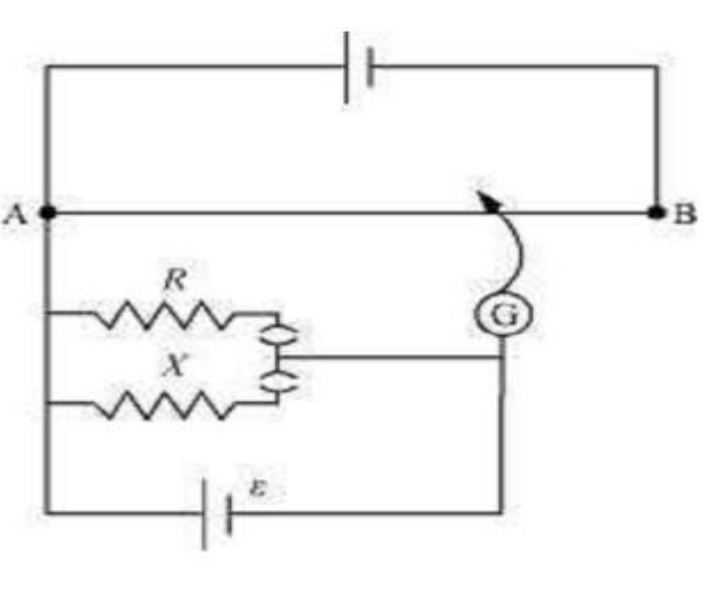
Answer Resistance of the resistor, R = 10.0 Ω Balance point l1 = 58.3 cm Current in the potentiometer wire = i Hence, potential drop across R, Resistance of the unknown resistor = X Balance point for this resistor, l2 = 68.5 cm Hence, potential drop across X,

Therefore, the value of the unknown resistance, X, is 11.75 Ω. If we fail to find a balance point with the given cell of emf, ε, then the potential drop across R and X must be reduced by putting a resistance in series with it. Only if the potential drop across R or X is smaller than the potential drop across the potentiometer wire AB, a balance point is obtained.
Q.21 Figure shows a 2.0 V potentiometer used for the determination of internal resistance of a 1.5 V cell. The balance point of the cell in open circuit is 76.3 cm. When a resistor of resistance 9.5 Ω is used in the external circuit of the cell, the balance point shifts to 64.8 cm length of the potentiometer wire. Determine the internal resistance of the cell.
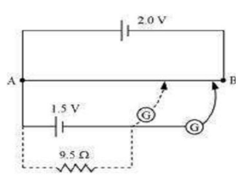
Answer Internal resistance of the cell = r Balance point of the cell in open circuit, l1 = 76.3 cm. An external resistance (R) is connected to the circuit with R = 9.5 Ω New balance point of the circuit, l2 = 64.8 cm Current flowing through the circuit = I
The relation connecting resistance and emf is, r =

Therefore, the internal resistance of the cell is 1.68Ω.
2(c) Heating Effect of Current
21. Electrical Energy:
Electrical energy is the energy derived from electric potential energy or kinetic energy of the charged particles. In general, it is referred to as the energy that has been converted from electric potential energy. We can define electrical energy as the energy generated by the movement of electrons from one point to another. The movement of charged particles along/through a medium (say wire) constitutes current or electricity.
Units of Electrical Energy:
The basic unit of electrical energy is the joule or watt-second. An electrical energy is said to be one joule when one ampere of current flows through the circuit for a second when the potential difference of one volt is applied across it. The commercial unit of electrical energy is the kilowatt-hour (kWh) which is also known as the Board of trade unit (B.O.T).
Generally, one kwh is called one unit.
Some examples of electrical energy:
A few examples of electrical energy are:
- In a car battery, a chemical reaction results in the formation of an electron which possesses the energy to move in an electric current. These moving charges provide electrical energy to the circuits in the car.
- Lightning, during a thunderstorm, is an example of electrical energy – what we see as lightning is nothing but electricity discharging in the atmosphere.
- Electric eels generate electrical energy and use it against predators for defense.
Electrical Energy into Mechanical Energy:
Electrical energy can be converted into other forms of energy like heat energy, light energy, motion etc. The best-known examples are:
- Fan: The motor in Fan converts electrical energy into mechanical energy
- Bulb: Here the electrical energy is converted into light energy.
22. Electric Power:
It is the rate at which work is done or energy is transformed in an electrical circuit. Simply put, it is a measure of how much energy is used in a span of time.
In physics, the rate of transfer of electrical energy by an electrical circuit per unit time is called electrical power. Here electrical energy can be either kinetic energy or potential energy. In most of the cases, potential energy is considered, which is the energy stored due to the relative positions of charged particles or electric fields. Electrical power is denoted by P and measured using Watt equal to one joule per second…
23. Joule’s law of heating effect:
The joule’s first law shows the relationship between heats produced by flowing electric current through a conductor.
Q = I2 R T
Where,
- The amount of generated heat is proportional to the wire’s electrical resistance when the current in the circuit and the flow of current is not changed.
- The amount of generated heat in a conductor carrying current is proportional to the square of the current flow through the circuit when the electrical resistance and current supply is constant.
- The amount of heat produced because of the current flow is proportional to the time of flow when the resistance and current flow is kept constant.
-: Some Important Mcq:-
- The resistivity of a conductor with increase in temperature increase.
- With increase in temperature the mobility of electron
- With the increase in length of conductor, its resistivity does not change.
(4). If we halve the area of cross section of a conductor resistance of the conductor will be
(a) Double (b) Half (c) Four times (d) One fourth
(5). Electron mobility & resistivity of metallic conductor are related by the relation
(a) (b) ρ ∝μ (c) (d)
(6). If we increase the length of metallic conductor by 2 times resistivity of metallic conductor becomes
(A) 2 times (b) Half (c) Remains constant (d) None of these
(7). S.I. unit of conductivity is
(a)Ohm (b) mho (c) Ohm-m (d)
(8). Resistivity of the material is independent of
(a)Nature of material (b) Temperature of material (c) Dimensions of material (d) none of these
(9). When electron moves from a wire having a larger area of cross section to a smaller one, the drift velocity of electron
(a) Decrease (b) Increase (c) Remain constant (d) None of the above
(10). For insulator, with increase in temperature resistivity wills 25
(a) Increase (b) Decrease (c) Becomes zero (d) remains constant
(11). Resistivity of semiconductor with increase in temperature will
(a)Increase (b) Decrease (c) Remains constant (d) none of the above
(12). Which of the following is not a unit of electric power
(a)Joule/sec (b) Kilowatt hour (c) Ampere-volt (d) Watt
(13). A bulb of 4.84 Ω is producing light when connected to 220 v supply what is the electric power of bulb
(A) 75 watt (b) 100 watt (c) 125 watt (d) 200 watt
Q14. Kirchhoff’s junction rule is based on –
(a) Law of conservation of energy (b) law of conservation of momentum
(c) Law of conservation of charge (d) none of these
Q15. Kirchhoff’s second law is based on law of conservation of –
(a) Sum of mass & energy (b) momentum (c) energy (d) charge
Q16. For the Kirchhoff’s junction rule which of the following is correct –
(a) There is no accumulation of charge at junction point (b) algebraic sum of current at junction is zero
(c) It applies to both open and closed circuit (d) all of above
Q17. A galvanometer acting as a voltmeter will have with its coil
(a) A high resistance in parallel (b) a high resistance in series
(c) A low resistance in parallel (d) a low resistance in series
Q18. Emf of cell is measured in
- joule (b) joule/coulomb (c) joule-coulomb (d) joule/coulomb/meter
Q19. Potentiometer measures the potential difference more accurately than a voltmeter because
(a) It has a wire of high resistance (b) It has a wire of low resistance
(c) It does not draw current from external circuit (d) it draws heavy current from external
Q20. Copper wire is used as connecting wire because
- copper has high electrical resistance (b) copper has low electrical resistance
(c) Copper has low electrical conductivity (d) copper has high value at elasticity
Q21. Ohm’s law is valid when temperature if conductor is
(a) Very low (b) very high (c) varying (d) constant
Q22. While measuring emf of cell potentiometer acts as ideal voltmeter of
- high resistance (b) low resistance (c) infinite resistance (d) zero resistance
Q23. Constantan wire is used for making standard resistance, because it has
(a) High melting point (b) low specific resistance
(c) High specific resistance (d) negligible temperature coefficient of resistance
Q24. Appliances based on heating effect of current work on
(a) Only a.c. (b) Only d.c. (c) Both a.c. and d.c. (d) None of these
Q25. Potentiometer is based on
(a) Deflection method (b) zero deflection method (c) both (a) and (b) (d) None of these
Directions: Read the following questions and choose
(A) If both the statements are true and statement-2 is the correct explanation of statement-1.
(B) If both the statements are true but statement-2 is not the correct explanation of statement-1.
(C) If statement-1 is True and statement-2 is False.
(D) If statement-1 is False and statement-2 is True.
- Statement-1: There is no current in the metals in the absence of electric field.
Statement-2: Motion of free electrons are random.
(a) (A) (b) (B) (c) (C) (d) (D)
- Statement-1: In meter bridge experiment, a high resistance is always connected in series with a galvanometer.
Statement-2: As resistance increases current through the circuit increases.
(a) (A) (b) (B) (c) (C) (d) (D)
- Statement-1: A potentiometer of longer length is used for accurate measurement.
Statement-2: The potential gradient for a potentiometer of longer length with a given source of emf becomes small.
(a) (A) (b) (B) (c) (C) (d) (D)
- Statement-1: Potential difference across the battery is always equal to emf of the battery.
Statement-2: Work done by the battery per unit charge is the emf of the battery.
(a) A (b) B (c) C (d) D
- Statement-1: In a simple battery circuit the point at the lowest potential is positive terminal of the battery.
Statement-2: The current flows towards the point of the lower potential in the circuit, but it does not flow in a cell from positive to the negative terminal.
(a) (A) (b) (B) (c) (C) (d) (D)
IMPORTANT QUESTION:-
- STATE AND EXPLAIN DRIFT VELOCITY……………………………………………..(3)
- EXPLAIN OHM’S LAW……………………………………………………………………(2)
- DERIVE EXPRESSION FOR INTERNAL RESISTANCE OF A CELL…………………(3)
- EXPLAIN METRE BRIDGE OR SLIDE WIRE BRIDGE………………………………..(5)
- EXPLAIN POTENTIOMETER WITH ONE APPLICATION…………………………….(5)
- GIVE THE FACTOR ON WHICH RESISTANCE OF A CONDUCTOR DEPENDS…..(2)
- GIVE DIFFERENCE BETWEEN EMF AND TERMINAL POTENTIAL DIFFERENCE.(2)
To download Current Electricity notes click on the link
wait few second to upload pdf………………………